Scripts/pl: Difference between revisions
(Created page with "Wprowadźmy operacje logiczne. Jako przykład początkowy umieść te linie po {{incode|base_cyl(...}}, to utworzy metodę dla operacji '''Fusion''' znanej również jako '''Union''':") |
(Created page with "Tutaj również nie ma nic wyjątkowego, należy jednak zwrócić uwagę na jednolitość kodowania metod; to podejście jest bardziej liniowe niż te spotykane w innych samouczkach dotyczących skryptów, ta "liniowość" znacznie pomaga w czytelności, a także w operacjach wycinania, kopiowania i wklejania.") |
||
| Line 151: | Line 151: | ||
}} |
}} |
||
Tutaj również nie ma nic wyjątkowego, należy jednak zwrócić uwagę na jednolitość kodowania metod; to podejście jest bardziej liniowe niż te spotykane w innych samouczkach dotyczących skryptów, ta "liniowość" znacznie pomaga w czytelności, a także w operacjach wycinania, kopiowania i wklejania. |
|||
Nothing exceptional also here, note however the uniformity in method coding; This approach is more linear that those seen around other tutorial on scripting, this "linearity" help greatly in readability and also with cut-copy-paste operations. |
|||
Let's use the geometries, delete lines below the code section starting with {{incode|# objects definition}}, and insert the following lines: |
Let's use the geometries, delete lines below the code section starting with {{incode|# objects definition}}, and insert the following lines: |
||
Revision as of 07:08, 24 October 2023
| Temat |
|---|
| Tworzenie skryptów |
| Poziom trudności |
| Podstawowy |
| Czas wykonania |
| Autorzy |
| onekk Carlo |
| Wersja FreeCAD |
| 0.19 |
| Pliki z przykładami |
| Zobacz również |
| - |
Wprowadzenie
Przez tworzenie skryptów rozumiemy tworzenie obiektów topologicznych za pomocą interpretera Python dla FreeCAD. Program FreeCAD może być używany jako "bardzo dobry" zamiennik OpenSCAD, głównie dlatego, że ma prawdziwy interpreter środowiska Python, co oznacza, że ma na pokładzie prawdziwy język programowania, prawie wszystko, co można zrobić z GUI, można zrobić za pomocą skryptu Python.
Niestety informacje na temat skryptów w dokumentacji, a nawet na tej Wiki, są rozproszone i brakuje im jednolitości "pisania”, a większość z nich jest wyjaśniona w zbyt techniczny sposób.
Zaostrzenie apetytu
Pierwszą przeszkodą w łatwej drodze do tworzenia skryptów jest to, że nie ma bezpośredniego sposobu na dostęp do wewnętrznego edytora Python FreeCAD poprzez pozycję menu lub ikonę na pasku narzędzi, ale wiedząc, że FreeCAD otwiera plik z rozszerzeniem .py w wewnętrznym edytorze Python, najprostszą sztuczką jest utworzenie go w ulubionym edytorze tekstu, a następnie otwarcie go za pomocą zwykłego polecenia Plik → Otwórz.
Aby zrobić to w uprzejmy sposób, plik musi być napisany w pewnym porządku, edytor FreeCAD Python ma dobre podświetlanie składni, którego brakuje w wielu prostych edytorach, takich jak Notatnik Windows lub niektóre podstawowe edytory Linuksa, więc wystarczy napisać te kilka linijek:
"""script.py

   Primo script per FreeCAD

"""
Zapisz je ze znaczącą nazwą z rozszerzeniem .py i załaduj wynikowy plik w FreeCAD, za pomocą wspomnianego polecenia Plik → Otwórz.
Minimalny przykład tego, co jest niezbędne w skrypcie, jest pokazany w tym fragmencie kodu, który można wykorzystać jako szablon dla prawie każdego przyszłego skryptu:
"""filename.py

   Here a short but significant description of what the script do

"""

import FreeCAD
from FreeCAD import Base, Vector
import Part
from math import pi, sin, cos

DOC = FreeCAD.activeDocument()
DOC_NAME = "Pippo"

def clear_doc():
    """
    Clear the active document deleting all the objects
    """
    for obj in DOC.Objects:
        DOC.removeObject(obj.Name)

def setview():
    """Rearrange View"""
    FreeCAD.Gui.SendMsgToActiveView("ViewFit")
    FreeCAD.Gui.activeDocument().activeView().viewAxometric()

if DOC is None:
    FreeCAD.newDocument(DOC_NAME)
    FreeCAD.setActiveDocument(DOC_NAME)
    DOC = FreeCAD.activeDocument()
else:
    clear_doc()

# EPS= tolerance to use to cut the parts
EPS = 0.10
EPS_C = EPS * -0.5
Powyższy kod zawiera kilka sztuczek:
import FreeCADTa linia importuje FreeCAD w interpreterze FreeCAD Python, może wydawać się zbędna, ale tak nie jest.from FreeCAD import Base, VectorBase i Vector są szeroko stosowane w skryptach FreeCAD, importowanie ich w ten sposób pozwoli zaoszczędzić na wywoływaniu ich za pomocąFreeCAD.VectorlubFreeCAD.BasezamiastBaselubVector, zaoszczędzi to wiele naciśnięć klawiszy i sprawi, że linie kodu będą znacznie krótsze.
Zacznijmy od małego skryptu, który wykonuje bardzo małą pracę, ale pokazuje moc tej metody.
def cubo(nome, lung, larg, alt):
    obj_b = DOC.addObject("Part::Box", nome)
    obj_b.Length = lung
    obj_b.Width = larg
    obj_b.Height = alt

    DOC.recompute()

    return obj_b

# objects definition

obj = cubo("test_cube", 5, 5, 5)

setview()
Umieść te linie po kodzie "szablonu" i naciśnij zieloną strzałkę na pasku narzędzi "Makrodefinicje".
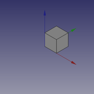
Zobaczysz kilka magicznych rzeczy, otworzy się nowy dokument o nazwie "Pippo" (włoska nazwa Goofy), a w widoku 3D zobaczysz Sześcian, taki jak na poniższym obrazku.
Coś więcej ...
Nie jest to zbyt niesamowite? Tak, ale musimy od czegoś zacząć, możemy zrobić to samo z walcem, dodając te linie kodu po metodzie cubo() i przed linią: # objects definition.
def base_cyl(nome, ang, rad, alt ):
    obj = DOC.addObject("Part::Cylinder", nome)
    obj.Angle = ang
    obj.Radius = rad
    obj.Height = alt

    DOC.recompute()

    return obj
Nawet tutaj nie ma nic zbyt ekscytującego. Warto jednak zwrócić uwagę na kilka osobliwości:
- Brak zwykłego odniesienia do
App., obecnego w wielu fragmentach kodu Dokumentacji, jest zamierzony, kod ten może być użyty nawet do wywołania FreeCAD jako modułu w zewnętrznym interpreterze Pythona, nie jest to łatwe do zrobienia z AppImage, ale z pewną ostrożnością można to zrobić. Plus w standardowym motto Pythona, że "lepiej jawnie niż niejawnie"App.wyjaśnia w bardzo "kiepski" sposób, skąd pochodzą rzeczy. - Zwróć uwagę na użycie "stałej" nazwy przypisanej do aktywnego Dokumentu w
DOC=FreeCAD. activeDocument(); activeDocument nie jest "stałą" w ścisłym sensie, ale w sposób "semantyczny" jest naszym "aktywnym dokumentem", który dla naszego użytku jest właściwą "stałą", więc konwencja Pythona polega na używaniu nazwy "ALL CAPS" dla "stałych", nie wspominając o tym, żeDOCjest znacznie krótszy niżFreeCAD.activeDocument(). - Każda metoda zwraca geometrię, będzie to jasne w dalszej części strony.
- Geometria nie miała właściwości
Placement, podczas używania prostych geometrii do tworzenia bardziej złożonych geometrii, zarządzaniePlacementjest kłopotliwe.
Co teraz zrobić z tą geometrią?
Wprowadźmy operacje logiczne. Jako przykład początkowy umieść te linie po base_cyl(..., to utworzy metodę dla operacji Fusion znanej również jako Union:
def fuse_obj(nome, obj_0, obj_1):
    obj = DOC.addObject("Part::Fuse", nome)
    obj.Base = obj_0
    obj.Tool = obj_1
    obj.Refine = True
    DOC.recompute()

    return obj
Tutaj również nie ma nic wyjątkowego, należy jednak zwrócić uwagę na jednolitość kodowania metod; to podejście jest bardziej liniowe niż te spotykane w innych samouczkach dotyczących skryptów, ta "liniowość" znacznie pomaga w czytelności, a także w operacjach wycinania, kopiowania i wklejania.
Let's use the geometries, delete lines below the code section starting with # objects definition, and insert the following lines:
# objects definition

obj = cubo("cubo_di_prova", 5, 5, 5)

obj1 = base_cyl('primo cilindro', 360,2,10)

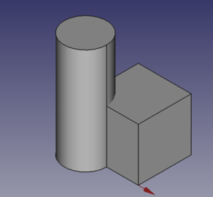
fuse_obj("Fusione", obj, obj1)

setview()
Launch the script with the green arrow and we will see in the 3D view something like:
Placement
Placement Concept is relatively complex, see Aeroplane Tutorial for a more deep explanation.
We usually are in need of placing geometries respect each other, when building complex object this is a recurring task, the most common way is to use the geometry Placement property.
FreeCAD offer a wide choice of ways to set this property, one is more tailored to another depending the knowledge and the background of the user, but the more plain writing is explained in the cited Tutorial, it use a peculiar definition of the Rotation portion of Placement, quite easy to learn.
FreeCAD.Placement(Vector(0, 0, 0), FreeCAD.Rotation(10, 20, 30), Vector(0, 0, 0))
But over other consideration, one thing is crucial, geometry reference point, in other word the point from which the object is modeled by FreeCAD, as described in this table, copied from Placement:
| Object | Reference Point |
|---|---|
| Part.Box | left (minx), front (miny), bottom (minz) vertex |
| Part.Sphere | center of the sphere (ie centre of bounding box) |
| Part.Cylinder | center of the bottom face |
| Part.Cone | center of bottom face (or apex if bottom radius is 0) |
| Part.Torus | center of the torus |
| Features derived from Sketches | the Feature inherits the Position of the underlying Sketch. Sketches always start with Position = (0, 0, 0). This position corresponds to the origin in the sketch. |
This information has to be kept in mind especially when we have to apply a rotation.
Some examples may help, delete all the line after base_cyl method and insert the portion of code below:
def sfera(nome, rad):
    obj = DOC.addObject("Part::Sphere", nome)
    obj.Radius = rad

    DOC.recompute()

    return obj

def mfuse_obj(nome, objs):
    obj = DOC.addObject("Part::MultiFuse", nome)
    obj.Shapes = objs
    obj.Refine = True
    DOC.recompute()

    return obj

def aeroplano():

    lung_fus = 30
    diam_fus = 5
    ap_alare = lung_fus * 1.75
    larg_ali = 7.5
    spess_ali = 1.5
    alt_imp = diam_fus * 3.0
    pos_ali = (lung_fus*0.70)
    off_ali = (pos_ali - (larg_ali * 0.5))

    obj1 = base_cyl('primo cilindro', 360, diam_fus, lung_fus)

    obj2 = cubo('ali', ap_alare, spess_ali, larg_ali, True, off_ali)

    obj3 = sfera("naso", diam_fus)
    obj3.Placement = FreeCAD.Placement(Vector(0, 0, lung_fus), FreeCAD.Rotation(0, 0, 0), Vector(0, 0, 0))

    obj4 = cubo('impennaggio', spess_ali, alt_imp, larg_ali, False, 0)
    obj4.Placement = FreeCAD.Placement(Vector(0, alt_imp * -1, 0), FreeCAD.Rotation(0, 0, 0), Vector(0, 0, 0))

    objs = (obj1, obj2, obj3, obj4)

    obj = mfuse_obj("Forma esempio", objs)
    obj.Placement = FreeCAD.Placement(Vector(0, 0, 0), FreeCAD.Rotation(0, 0, -90), Vector(0, 0, pos_ali))

    DOC.recompute()

    return obj

# objects definition

aeroplano()

setview()
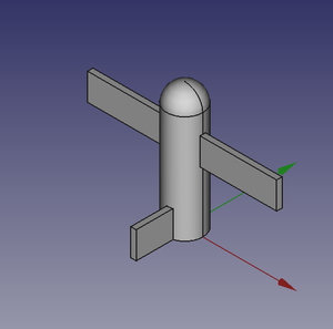
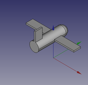
Let's explain something in the code:
- We have used a method to define a sphere, using the most easy definition, using only the radius.
- We have introduced a second writing for the Union or Fusion, using multiple objects, not more distant from the usual Part::Fuse it uses Part:Multifuse. We only use one property
Shapes. We have passed a tuple as arguments, but it accepts also a list. - We have defined a complex object aeroplano (italian word for aeroplane), but we have done it in a "parametric" way, defining some parameters and deriving other parameters, through some calculation, based on the main parameters.
- We have used some Placement
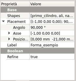
Placementpoperties around in the method and before returning the final geometries we have used aRotationproperty with the Yaw-Pitch-Roll writing. Note the lastVector(0, 0, pos_ali), that define a center of rotation of the whole geometry.
 |
 |
 |
It can be easily noted that aeroplano geometry rotate around his "barycenter" or "center of gravity", that I've fixed at wing center, a place that is relatively "natural", but could be placed wherever you want.
The first Vector(0, 0, 0) is the Translation vector, not used here, but if you substitute aeroplano() with these lines:
obj_f = aeroplano()

print(obj_F.Placement)
You will see in the Report window this text:
Placement [Pos=(0, -21, 21), Yaw-Pitch-Roll=(0, 0, -90)]
What has happened?
FreeCAD has translated the Vector(0, 0, 0), FreeCAD.Rotation(0, 0, -90), Vector(0, 0, pos_ali) in other word our Placement definition that specifies three components, Translation', Rotation and center of rotation in the "internal" values of only two components, Translation and Rotation.
you can easily visualize the value of pos_ali using a print statement in the aeroplano(... method and see that it is:
pos ali = 21.0
in other word the rotation center of the geometry is at Vector(0, 0, 21), but this rotation center is not shown in the GUI, it could be entered as a Placement value, it could not be easily retrieved.
This is the meaning of the word "awkward" that I've used to define Placement property.
- Tworzenie skryptów FreeCAD: Python, Wprowadzenie do środowiska Python, Poradnik: Tworzenie skryptów Python, Podstawy tworzenia skryptów FreeCAD
- Moduły: Moduły wbudowane, Jednostki miar, Ilość
- Środowiska pracy: Tworzenie Środowiska pracy, Polecenia Gui, Polecenia, Instalacja większej liczby Środowisk pracy
- Siatki i elementy: Skrytpy w Środowisku Siatek, v, Konwerska Mesh na Part, PythonOCC
- Obiekty parametryczne: Obiekty tworzone skryptami, Obsługa obrazu (Ikonka niestandardowa w widoku drzewa)
- Scenegraph: Coin (Inventor) scenegraph, Pivy
- Interfejs graficzny: Stworzenie interfejsu, Kompletne stworzenie interfejsu w środowisku Python (1, 2, 3, 4, 5), PySide, PySide examples początkujący, średniozaawansowany, zaawansowany
- Makrodefinicje: Makrodefinicje, Instalacja makrodefinicji
- Osadzanie programu: Osadzanie programu FreeCAD, Osadzanie GUI FreeCAD
- Pozostałe: Wyrażenia, Wycinki kodu, Funkcja kreślenia linii, Biblioteka matematyczna FreeCAD dla wektorów (deprecated)
- Węzły użytkowników: Centrum użytkownika, Centrum Power użytkowników, Centrum programisty