Tworzenie prostej części za pomocą środowiska pracy Rysunek Roboczy i Część
| Temat |
|---|
| Modelowanie |
| Poziom trudności |
| Początkujący |
| Czas wykonania |
| 1.5 godziny |
| Autorzy |
| heda |
| Wersja FreeCAD |
| 0.19 lub nowszy |
| Pliki z przykładami |
| nie dołączono |
| Zobacz również |
| Środowisko Część: Tworzenie prostej części, Tworzenie prostej części za pomocą środowiska pracy Rysunek Roboczy i Część |
Wprowadzenie
Ten poradnik ma na celu wykorzystanie go jako pierwsze wprowadzenie do środowiska pracy Rysunek Roboczy w programie FreeCAD. Poradnik wykorzystuje kształt 2D do stworzenia bryły 3D, co jest realizowane za pomocą środowiska Część. Zaleca się, aby czytelnik najpierw zapoznał się z poradnikiem Środowisko Część: Tworzenie prostej części, który tworzy ten sam model przy użyciu innej techniki, jednocześnie obejmując więcej podstaw interfejsu użytkownika programu FreeCAD. Ten poradnik oczekuje od użytkownika krótkiej znajomości zarówno interfejsu użytkownika jak i niektórych przepływów pracy dostępnych w FreeCAD. Poradnik jest tak skomponowany, że jego celem nie jest koniecznie pokazanie najbardziej efektywnego sposobu korzystania z programu, ale raczej uświadomienie czytelnikowi różnych funkcjonalności dostępnych w FreeCAD, jak z nich korzystać i gdzie je znaleźć.
Przewodnik zawiera następujące zagadnienia
- Model do wykonania,
- Tworzenie profilu 2D,
- Dlaczego wyciąganie może się nie udać,
- Wyciskanie profilu,
- Tworzenie otworu przelotowego,
- Tworzenie szkicu z profilu 2D,
- Jakość modeli,
- Zakończenie.
Model do wykonania
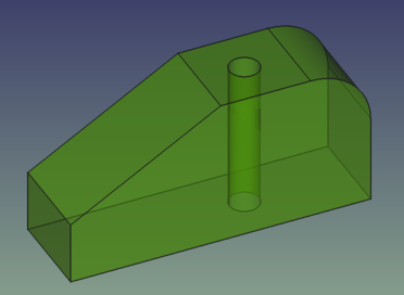
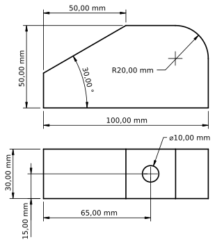
Tworzenie profilu 2D
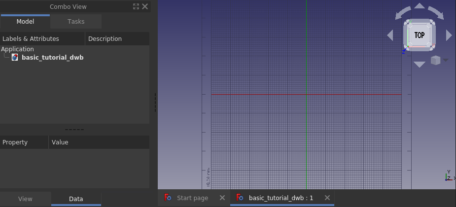
Utwórz nowy dokument i zapisz go odrazu pod nową nazwą. Zmień widok na Od góry i uruchom środowisko pracy
Rysunek Roboczy, Twój ekran powinien wyglądać jak poniżej. Jeśli siatka nie jest widoczna, przełącz ją za pomocą przycisku
Pokaż / ukryj siatkę.
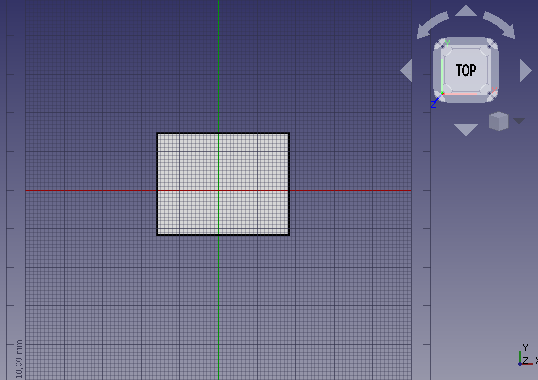
Aby rozpocząć profil, narysuj dowolny Prostokąt na płaszczyźnie XY, klikając 2 punkty w oknie widoku 3D tworzące dowolną przekątną prostokąta. Po wywołaniu polecenia otworzy się panel zadań, tym razem nie będziemy z niego korzystać, ale możesz oczywiście bezpośrednio wprowadzić współrzędne prostokąta. Twój widok 3D powinien mieć teraz narysowany prostokąt, podobny do tego z poniższego obrazka.
Podczas pracy w środowisku Rysunek Roboczy prawie zawsze rysuje się na płaszczyźnie 2D. Ta płaszczyzna 2D nazywana jest Płaszczyzną roboczą i jeśli użyjemy ustawień domyślnych, zawsze automatycznie wyrówna się do aktualnego widoku 3D. Tak więc, dopóki profil 2D nie zostanie ukończony, najlepiej jest po prostu zachować widok Od góry (pozycję kamery) i nie bawić się w obracanie widoku. Jeśli zdarzyło Ci się go już przestawić, to przed rozpoczęciem jakiegokolwiek nowego polecenia w środowisku Rysunek Roboczy po prostu zmień z powrotem na widok Od góry.
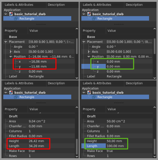
Widok z boku naszego finalnego modelu ma zewnętrzny obrys 100 x 50 mm i dobrze by było, gdyby lewy dolny róg był umieszczony w globalnej pozycji zerowej. Można to osiągnąć poprzez edytor właściwości. Upewnij się, że utworzony Prostokąt jest zaznaczony, następnie zmień Położenie prostokąta na (0, 0, 0), zmień Wysokość na 50mm i Długość na 100mm jak na poniższych obrazkach.
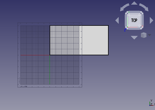
Prostokąt jest skończony i powinien wyglądać tak po zastosowaniu narzędzia Dopasuj wszystko do widoku.
Następnie rozbijemy prostokąt na jego cztery krawędzie, zrobimy to wybierając najpierw Prostokąt, a następnie wywołując polecenie Rozbij kształt, wypełnienie ściany zniknie, a obiekt w Widoku drzewa ma teraz nazwę Wire zamiast Rectangle, co widać na lewym obrazku poniżej. Ponowne wywołanie funkcji Rozbij kształt spowoduje rozbicie obiektu Wire na jego Krawędzie, co widać na środkowym obrazku poniżej.

Osoby spostrzegawcze zauważą, że ikona obiektu w widoku drzewa już dla krzywej łamanej zmieniła się na niebieski sześcian. Ten niebieski sześcian to ikona używana dla ogólnych obiektów geometrycznych (konkretnie obiektów geometrycznych środowisku pracy Projekt Części, ale to dla zaawansowanych czytelników). Zaznacz lewą pionową krawędź i wywołaj polecenie Ulepsz kształt, dawna krawędź będzie miała teraz inną ikonę i zmieniła etykietę na Linia. Jest to teraz obiekt środowiska Rysunek Roboczy, w którym można edytować na przykład punkt początkowy i punkt końcowy poprzez Edytor właściwości, nie jest to możliwe w przypadku obiektów krawędzi.
Tworzenie zaokrąglenia
Zacznij od zaznaczenia prawego górnego rogu krawędzi, użyj polecenia z menu Edycja → Zaznacz obszar, przytrzymaj
Lewy Przycisk Myszy (Left Mouse Button) i przeciągnij od prawej do lewej, a następnie zwolnij LMB. Podczas przeciągania od prawej do lewej wynikowy wybór obejmuje wszystko w całości lub częściowo w obszarze zaznaczenia. Przy przeciąganiu od lewej do prawej, w wynikowym zaznaczeniu znajdują się tylko obiekty w całości objęte obszarem zaznaczenia. Faktyczne zaznaczenie następuje po zwolnieniu lewego przycisku myszy i nie ma możliwości podglądu tego, co zostanie zaznaczone.

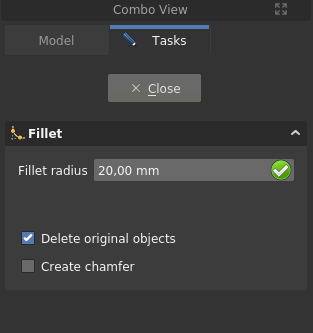
Mając zaznaczone krawędzie w prawym górnym rogu, wywołaj polecenie Zaokrąglenie w środowisku pracy Rysunek Roboczy. Zaznacz Usuń oryginalne obiekty i zmień wartość parametru promień na
20 mm i naciśnij klawisz Enter.
Zaokrąglenie zostało utworzone, a twój model powinien teraz wyglądać jak poniżej:

Tworzenie sfazowania
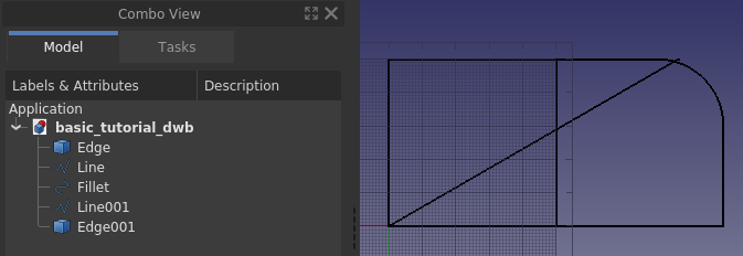
To make the chamfer we need to have a line with the correct inclination and also be able to position it correctly. Let us begin with the position, which is on coordinate (50, 50, 0). In the current profile we do not have a point there, so let’s create one by making a temporary help line. First select the left vertical Line, then create the help line by Duplicate selection in Edit → Duplicate selection, Line001 is created. Use the Property editor and move Line001 50 mm in x-direction using the Placement property. Next duplicate the lower horizontal edge, and change the angle of the edge to 30 degrees, once again using the Placement property. The model should now look like the image below.
Next, move the angled line into position. For this we make use of Draft Move along with the snap functionality in the Draft Workbench, more specifically end point snap. First make sure that your snap toolbar looks similar to below.

Then select the angled line, Edge001, press Move and a task panel opens up.
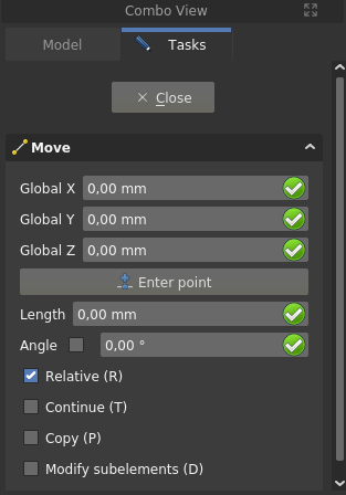
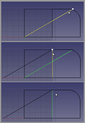
Make sure that Copy is unchecked. Hover the mouse over the upper quarter of the angled line, once the white dot is displayed at the right spot and the end point symbol shows, click the LMB. Move the mouse to the upper quarter of the help line, once the white dot and end point symbol appear, click the LMB. The sequence is illustrated below.
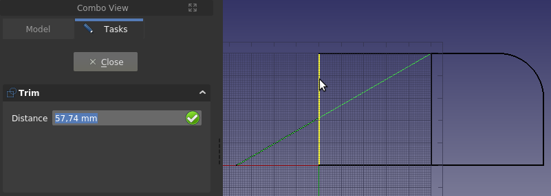
The line is now in the correct position, but it is too long. To adjust the length Draft Trimex will be used. Select the angled line, Edge001, press Trim and then click on the lower part of the left-most vertical line, Line, to use it as the cutting edge. The projection of the point where the cutting edge is selected onto the edge to be cut, determines the result. If you select the left-most vertical line near its top end, the wrong part of the angled line would be trimmed. The image below shows the Trim command invoked, the pre-selected vertical line, and the cursor hovering over the wrong end of that line. If you look carefully you can see the preview of the result.
Also trim the left-most vertical line to form the lower corner of the chamfer. Select the angled line, Edge001, near its top right endpoint for a correct result. If you make a mistake while trimming, just use Undo and
Refresh (the latter often called recompute) and try again.
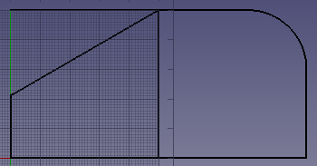
To trim the upper horizontal edge, the Fillet needs to be downgraded so that the upper edge is its own object in the Tree View. If you attempt to trim it without first having done the downgrade, the trimming function attempts to trim the arc in the fillet. Because the trimming edge, the middle vertical line, is perpendicular to the edge to be trimmed, you cannot control the trim result by picking a correct point on the trimming edge. Here you need the flip the default solution by holding down the Alt key as you select the cutting edge.
The profile is ready and shown below with the edges organized in a Group named Profile (or labeled to be precise in FreeCAD lingo), along with the help line deleted. Groups can be used to organize the features in your FreeCAD documents, its usage is similar to a folder structure on a computer’s file system. To move things in and out of the group, use drag and drop in the Tree View.
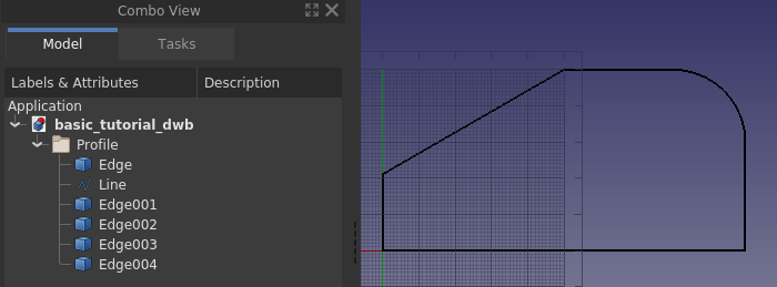
Dlaczego wyciskanie może się nie udać
Save the document. We will experiment in this paragraph and we want to be able to go back to the current model.
Let’s jump right in: select all the edges in the group Profile, and in the Part Workbench invoke the command
Extrude. A task panel opens, accept all the defaults and click OK.

That did not work out, but it sounds easy enough to fix the error, we just need to specify a direction. Click OK to get back to the task panel and select custom direction.
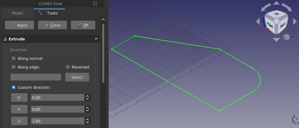
Accept the default z-axis and once more click OK.
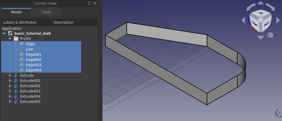
We managed to make a fence like structure, judging from the Tree View every edge is treated separately. It is not the filled solid that we want. Hit Undo, and let’s try something else.
Scrolling all the way to the bottom of the Extrude task panel there is an option Create solid, check that option and click OK.
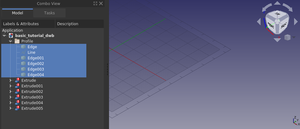
Everything disappeared, clearly that did not work either. Let’s go through why none of these ways are working. In the first case we got an error that the direction could not be determined. A flat face has a normal, i.e. direction, a line does not. Since from our second attempt we know that it worked when providing a direction, the error simply comes from trying to extrude a line without knowing a direction. The observant will say that an arc has a normal (direction), this is true. If you select only the edge that is the arc, FreeCAD will extrude it, also with default settings.
In the second case it worked, but we also got an extrusion for each edge we had in our selection. The resulting features however are not what we want, i.e. a solid.
In the third case we checked Create solid, and ended up with everything disappearing. The objects in the Tree View have a different icon as well, there is a white exclamation mark on a red background, that particular overlay icon means that the object has an error that has to be tended to. One can read up on the different types of overlay icons on the wiki.
Hovering over any of the Tree View objects with the overlay icon a tool tip is displayed, it says Wire is not closed.

In our case the error is not fixable. It is geometrically impossible to create a solid out of an extruded single line. An extruded line simply becomes a sheet, or shell in FreeCAD lingo. In other words, this is not a FreeCAD limitation, it is a fundamental outcome of geometrical theory. The reason why the 3D view goes completely blank is that the created features, or objects in the Tree View, have errors in the produced shape, and thus contain nothing to render. FreeCAD does however create the new document objects (in this case extrusions) and thus hides any geometry/object used for making the new document objects. That is why the screen goes blank when trying to make a solid out of a line, or lines.
The tool tip says it all, in order to extrude into a solid one needs a closed wire, or a face. A face is, per definition, simply a closed wire that is filled. One way to create a closed wire out of our profile edges is to select them all and apply Draft Upgrade. If applied once it becomes a wire, while at the same time it consumes the individual edges from the Tree View. If applied twice it becomes a face, either of those allows for a successful solid extrusion.
Before going on to the next paragraph: open the previous version of the document.
Wyciąganie profilu
Another way to create the closed wire is with the Shape builder command from the Part Workbench, which allows for making a wire without consuming the individual edges. Part Shape builder is a powerful tool to create any geometric entity in FreeCAD that can be used further to create complex solids, the simplest example is creating a line between two vertices. Click Part Shape builder to bring up the task panel.
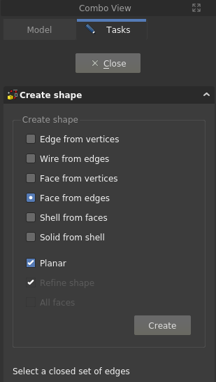
We can use either Wire from edges or Face from edges. Multiple selections have to be made with the Ctrl key pressed down. Let’s use Face from edges, once that option is selected one can also select Planar, do that as well. Then select all edges in the profile, the order does not matter (in this case) and click Create, and then Close to come back to the Tree View. The face has been created.
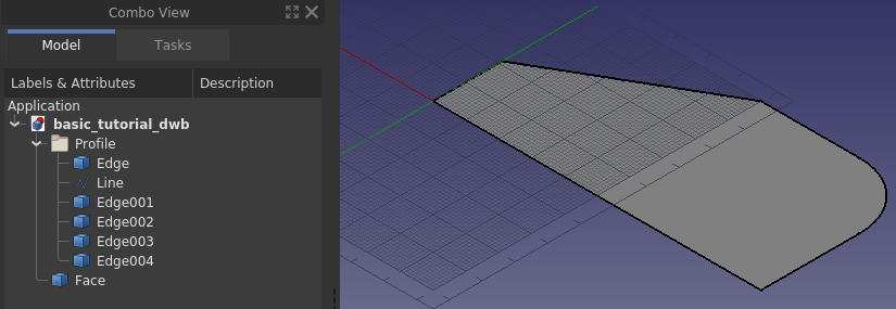
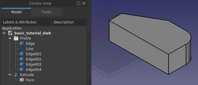
Select the Face and invoke Part Extrude, set the extrusion length to 30 mm and click OK.
Tworzenie otworu przelotowego
To make the through hole we need a cylinder correctly positioned to make a boolean cut with.
Create a cylinder, and position it correctly. In this case the radius is 5 mm, the height is set to 60 mm. For the placement, first it is rotated -90 degrees around the x-axis, then positioned at (65, -5, 15). The negative 5 in the y-direction is because the height is 10 mm longer than needed.
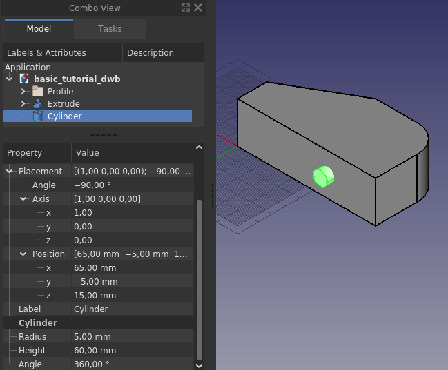
It does not hurt to make the height of the cylinder longer than needed. For a simple model like this it will not matter if the cylinder is the exact height of the profile. It is however good practice to avoid co-planar faces to prevent numerical errors in the geometric kernel that can sometimes result in strange effects, or failures in subsequent operations.
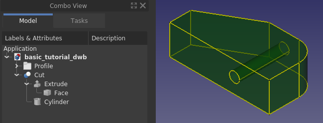
With a final boolean cut, and after changing the appearance of the resulting object, the model is completed.
Making a sketch out of the 2D profile
Using the Draft Workbench is one way of creating a 2D profile. In the Draft Workbench a wire can be made in 3D space. FreeCAD provides another tool to make 2D profiles – the Sketcher Workbench. Using a sketch is a more versatile way to create a 2D profile. Any 2D profile made in the Draft Workbench can be converted to an unconstrained sketch.
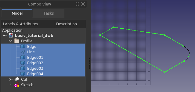
Start by hiding the Cut feature and make the edges in the profile visible. Select the edges and from the Draft Workbench press the toolbar button Draft to Sketch. You should see the same as in the image below.
Next, hide the original edges and double-click the Sketch object in the Tree View, bringing you to the following state, i.e. the Sketcher task panel opened.
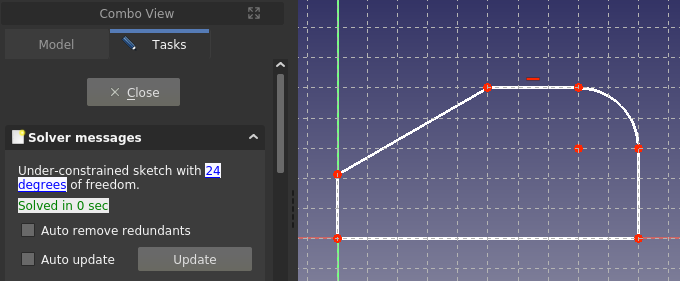
This is how it looks when one edits a sketch. Since this is not a tutorial for using the Sketcher just go ahead and close it. If you want an introduction to sketching, which is a core workflow in any 3D parametric CAD, please follow the sister tutorial Creating a simple part with PartDesign.
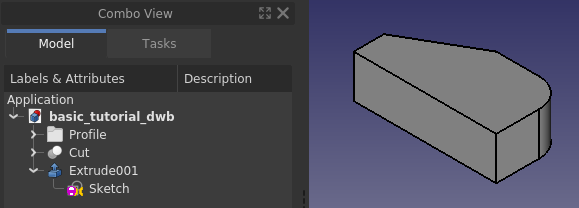
With the Sketch closed and selected, from the Part Workbench use Extrude in the same way as before. The basic block of the simple model is ready once again.
Jakość modelu
Sooner or later when working with 3D parametric CAD you will come across a broken model, either one you have made yourself, or a model that you have imported. A broken model can work for its purpose, but more often than not, there are subsequent operations that simply will not work. To repair a broken model one has to know what to repair, this is where the built-in quality check tools in FreeCAD come in.
First let us check the quality of the recently created Extrude001. With the Part Workbench active, first select Extrude001 and then use the command Check geometry. Check all settings checkboxes except the top one, and click the Run check button.
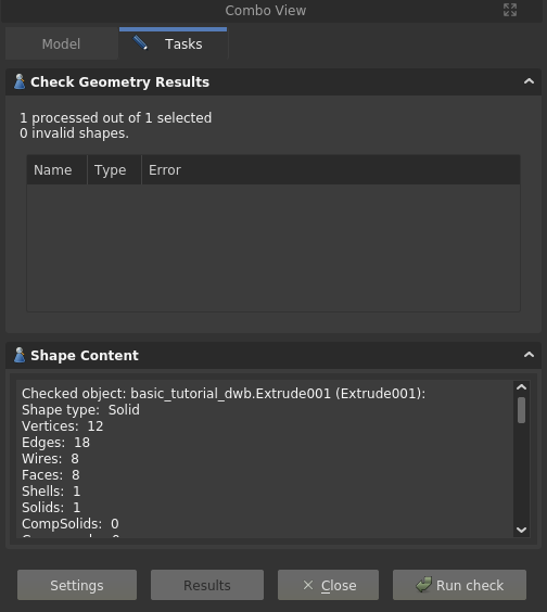
Our model is OK, no errors are reported. There is also a listing of the models content, or in FreeCAD lingo, the content of the shape, i.e. how it is put together from ground up. Here one can see that apparently to make a solid one also needs a shell, and the shell is made out of faces, and so on. In other words, you can create any solid by simply starting out by making points, or vertices, from those one makes edges, and from those one creates wires, and out of the wires one makes faces which are then stitched into a shell, from which one finally arrives at a solid. A solid can only be made from a watertight shell. A not watertight shell is a common source of troublesome CAD models, it can for example happen with imported geometry created in a different software, especially when using the commonly available neutral file formats.
Another check one can do is related to the Sketch. Close the task panel for the geometry check. Select the Sketch, expand Extrude001 in the Tree View if needed in order to see the sketch object. Switch to the Sketcher Workbench, use the command
Validate sketch, a task panel opens. In the task panel, click the Find button for Missing coincidences. It highlights and reports 6 of them, i.e. all the points where the edges meet.
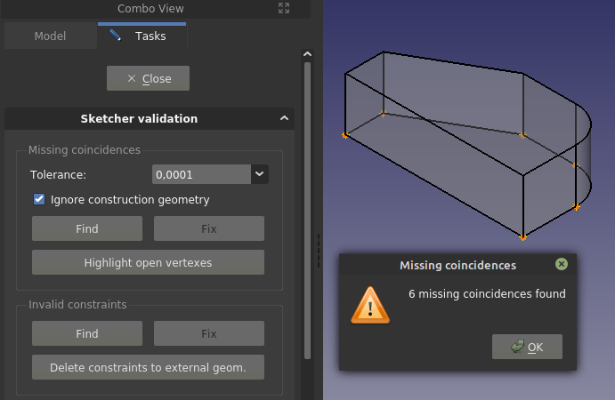
Kliknij przycisk OK w wyskakującym oknie dialogowym, a następnie kliknij przycisk Napraw, aby uzdrowić Brakujące zbieżności. Jeśli zamkniesz panel zadań, i przejdziesz do trybu edycji Szkicu, zgłosi on 12 stopni swobody, w przeciwieństwie do wcześniejszych 24. Zostało to osiągnięte poprzez dodanie zbieżnych wiązań do punktów końcowych krawędzi.
Uważny czytelnik zauważy, że podczas używania krawędzi ze środowiska pracy Rysunek Roboczy te musiały być połączone w zamkniętą łamaną, aby stworzyć wyciągnięcie bryły, podczas gdy w Szkicowniku nie było to najwyraźniej potrzebne. Logika jest taka, że szkic jest jednym obiektem, a wyciągnięcie jednego obiektu jest traktowane tak, jakby było zamkniętą łamaną (w tym przypadku).
Na koniec warto zaznaczyć, że choć tworzenie kolejnych obiektów ze szkiców z otwartymi wierzchołkami może działać, to najlepszą praktyką jest nie mieć żadnych, jak również mieć w pełni związany szkic (w przeciwieństwie do szkicu z niepełnym związaniem). Powodem, dla którego to działa jest to, że szkic jest tworzony z profilu Rysunku Roboczego skonstruowanego w taki sposób, że punkty końcowe krawędzi pasują do siebie bez żadnych przerw. Jeśli narysujesz ręcznie szkic i również spróbujesz dopasować punkty końcowe ręcznie, jest praktycznie gwarantowane, że punkty końcowe nie będą pasować, tj. luki (chociaż nie są naprawdę widoczne na ekranie) będą na tyle duże, że jądro geometryczne nie może uznać krawędzi za geometrycznie połączone.
Zakończenie
Po zakończeniu tego poradnika zapoznałeś się z podstawową funkcjonalnością programu FreeCAD, wraz z podstawowymi środowiskami pracy Część i Rysunek Roboczy. Jesteś również świadomy istnienia środowiska pracy Szkicownik, które dla wielu doświadczonych użytkowników jest jedynym narzędziem używanym do tworzenia profili 2D wykorzystywanych później w operacjach na elementach bryłowych. Używanie szkiców jest podstawową koncepcją środowiska Projekt Części. Sugeruje się, abyś nauczył się szkiców i środowiska Projekt Części w następnej kolejności, jeśli skupiasz się na tworzeniu brył. Siostrzany poradnik Projekt Części: tworzenie podstawowych brył tworzy ten sam model. Jeśli skupiasz się na modelowaniu budynków, powinieneś zapoznać się ze środowiskami pracy roboczymi Rysunek Roboczy i Architektura.
W końcu FreeCAD jest tworzony przez wolontariuszy w ich wolnym czasie. Jeśli chcesz dalej rozwijać możliwości programu, rozważ pomoc w rozwoju FreeCAD, na przykład poprzez poprawę dokumentacji.