Surface CurveOnMesh: Difference between revisions
(More clear steps on how to use the tool) |
(Left: mesh object with selected points on the surface. Right: splines created by picking several points. For future addition of images.) |
||
| Line 25: | Line 25: | ||
If the object is not a [[Mesh|Mesh]], but a parametric [[Shape|Shape]] or surface, it must be converted first to a mesh using {{Button|[[File:Mesh_FromPartShape.svg|16px]] [[Mesh_FromPartShape|Mesh FromPartShape]]}}. |
If the object is not a [[Mesh|Mesh]], but a parametric [[Shape|Shape]] or surface, it must be converted first to a mesh using {{Button|[[File:Mesh_FromPartShape.svg|16px]] [[Mesh_FromPartShape|Mesh FromPartShape]]}}. |
||
These edges created on top of the mesh may be further used to re-create the surface in a parametric way by using tools such as {{Button|[[File:Surface_GeomFillSurface.svg|16px]] [[Surface_GeomFillSurface|GeomFillSurface]]}} and {{Button|[[File:Surface_Sections.svg|16px]] [[Surface_Sections|Sections]]}}. |
|||
</translate> |
|||
[[File:Surface_CurveOnMesh_mesh_example.png]] [[File:Surface_CurveOnMesh_example.png]] |
|||
<translate> |
|||
{{Caption|Left: mesh object with selected points on the surface. Right: splines created by picking several points.}} |
|||
==Usage== <!--T:3--> |
==Usage== <!--T:3--> |
||
Revision as of 18:54, 2 October 2020
This documentation is not finished. Please help and contribute documentation.
GuiCommand model explains how commands should be documented. Browse Category:UnfinishedDocu to see more incomplete pages like this one. See Category:Command Reference for all commands.
See WikiPages to learn about editing the wiki pages, and go to Help FreeCAD to learn about other ways in which you can contribute.
|
|
| Menu location |
|---|
| Surface → CurveOnMesh |
| Workbenches |
| Surface |
| Default shortcut |
| None |
| Introduced in version |
| 0.17 |
| See also |
| None |
Description
Surface CurveOnMesh creates approximated spline segments on top of a selected mesh.
If the object is not a Mesh, but a parametric Shape or surface, it must be converted first to a mesh using Mesh FromPartShape.
These edges created on top of the mesh may be further used to re-create the surface in a parametric way by using tools such as GeomFillSurface and
Sections.
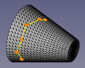
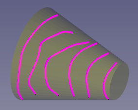
Left: mesh object with selected points on the surface. Right: splines created by picking several points.
Usage
- Make sure you have mesh object. This can be created by the
Mesh Workbench, or by importing a mesh file type, like STL, OBJ, or DAE. If a solid object or solid file type (STEP) is used, it can be converted to a mesh using
Mesh FromPartShape.
- Select the mesh, then press
Curve on mesh.
- Press Start.
- Using the mouse pointer, pick points on the surface of the mesh in the 3D view; pick as many points as necessary to draw a smooth preview line.
- When enough points have been added, right click on the 3D view to open the context menu, and select Create.
- Depending on how smooth the points were added, one object or multiple objects will be created in the tree view.
- Repeat the sequence Start → Pick → Create, to add more approximated splines.
- The new spline will be created, and will appear in the tree view, immediately after using Create; the task panel will remain active.
- Press Close to close the task panel, and terminate the command completely.
After pressing Start, the context menu (right-click) in the 3D view shows other options beside Create.
- Close wire: if at least three points have been picked, this option will be available to join the last point to the first point with a line. Then Create can be used to produced a closed spline.
- Clear: it will erase the tentative points that have been set up to this moment on the mesh, and will allow you to pick new ones.
- Cancel: it will erase the tentative points that have been set, and will stop the picking operation. To pick points once more, Start must be pressed again.
Options
Properties
- DataProperty: description of the property
- ViewProperty: description of the property

