Skripte
| Thema |
|---|
| Skripten |
| Niveau |
| Basis |
| Zeit zum Abschluss |
| Autoren |
| onekk Carlo |
| FreeCAD-Version |
| 0.19 |
| Beispieldateien |
| Siehe auch |
| None |
Einführung
Unter Skripten verstehen wir die Erstellung topologischer Objekte mit dem Python Interpreter von FreeCAD. FreeCAD könnte ein "sehr guter" Ersatz für OpenSCAD sein, vor allem, weil es einen echten Python Interpreter hat, das heißt, es hat eine echte Programmiersprache an Bord, fast alles, was man mit der GUI machen kann, ist mit einem Python Skript machbar.
Bedauerlicherweise sind die Informationen über das Skripten in der Dokumentation und sogar in diesem Wiki verstreut und es mangelt an Einheitlichkeit beim "Schreiben", und die meisten von ihnen werden zu technisch erklärt.
Befeuchte deinen Appetit
Das erste Hindernis auf einem einfachen Weg zur Skripterstellung ist, dass es keine direkte Möglichkeit gibt, den FreeCAD internen Python Editor über einen Menüeintrag oder ein Symbol im Werkzeugleistenbereich aufzurufen, aber wenn man weiß, dass FreeCAD eine Datei mit der Erweiterung .py im internen Python Editor öffnet, ist der einfachste Trick, sie in Ihrem bevorzugten Texteditor zu erstellen und sie dann mit dem üblichen Befehl Datei → Öffnen zu öffnen.
Um die Dinge in einer höflichen Art und Weise zu machen, muss die Datei mit einer gewissen Ordnung geschrieben werden, FreeCAD Python Editor haben eine gute "Syntax Hervorhebung", die in vielen einfachen Editoren wie Windows Notepad oder einige grundlegende Linux Editoren fehlt, so ist es ausreichend, diese wenigen Zeilen zu schreiben:
"""script.py

   Primo script per FreeCAD

"""
Speichere sie mit einem aussagekräftigen Namen mit der Erweiterung .py und lade die resultierende Datei in FreeCAD, mit dem besagten Datei - Öffnen Befehl.
Ein Minimalbeispiel dafür, was in einem Skript enthalten sein muss, wird in diesem Teil des Codes gezeigt, den du als Vorlage für fast jedes zukünftige Skript verwenden könntest:
"""filename.py

   Here a short but significant description of what the script do

"""


import FreeCAD
from FreeCAD import Base, Vector
import Part
from math import pi, sin, cos

DOC = FreeCAD.activeDocument()
DOC_NAME = "Pippo"

def clear_doc():
    """
    Clear the active document deleting all the objects
    """
    for obj in DOC.Objects:
        DOC.removeObject(obj.Name)

def setview():
    """Rearrange View"""
    FreeCAD.Gui.SendMsgToActiveView("ViewFit")
    FreeCAD.Gui.activeDocument().activeView().viewAxometric()


if DOC is None:
    FreeCAD.newDocument(DOC_NAME)
    FreeCAD.setActiveDocument(DOC_NAME)
    DOC = FreeCAD.activeDocument()

else:

    clear_doc()

# EPS= tolerance to use to cut the parts
EPS = 0.10
EPS_C = EPS * -0.5
Der obige Code enthält einige Tricks:
import FreeCADDiese Zeile importiert FreeCAD in den FreeCAD Python Interpreter, es mag überflüssig erscheinen, ist es aber nichtvon der FreeCAD Importbasis, VektorBasis und Vektor sind in FreeCAD Skipten weit verbreitet. Wenn du sie auf diese Weise importierst, ersparst du dir den Aufruf mitFreeCAD.VectoroderFreeCAD.Baseanstelle vonBasisoderVektor, dies erspart viele Tastatureingaben und macht Codezeilen viel kleiner.
Lasse uns mit einem kleinen Skript anfangen, das eine sehr kleine Arbeit leistet, aber die Kraft dieses Ansatzes zeigt.
def cubo(nome, lung, larg, alt):
    obj_b = DOC.addObject("Part::Box", nome)
    obj_b.Length = lung
    obj_b.Width = larg
    obj_b.Height = alt

    DOC.recompute()

    return obj_b

# objects definition

obj = cubo("test_cube", 5, 5, 5)

setview()
Setze diese Zeilen nach dem "Vorlage" Code und drücke den grünen Pfeil in der Makro Werkzeugleiste
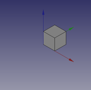
Du wirst einige magische Dinge sehen, ein neues Dokument mit dem Namen "Pippo" (italienischer Name von Goofy') ist geöffnet, und du wirst in der 3D Ansicht einen Würfel sehen, wie in der Abbildung unten.
Etwas mehr...
Not too amazing? Yes, but we have to start somewhere, we can do the same thing with a Cylinder, add these lines of code after the cubo( method and before the line # objects definition.
def base_cyl(nome, ang, rad, alt ):
    obj = DOC.addObject("Part::Cylinder", nome)
    obj.Angle = ang
    obj.Radius = rad
    obj.Height = alt

    DOC.recompute()

    return obj
Even here nothing too exciting. But please note some peculiarities:
- The absence of the usual reference to the
App., present in many Documentation code snippets, is deliberate, this code could be used even invoking FreeCAD as a module in an external Python interpreter, the thing is not easily doable with an AppImage, but with some care it could be done. Plus in the standard Python motto that "better explicit than implicit"App.is explaining in a very "poor" way where the things are from. - note the use of the "constant" name assigned to the active Document in
DOC=FreeCAD.activeDocument(); active Document is not a "constant" in a strict sense, but in a "semantical" way is our "active Document", that for our use is a proper "constant" so the Python convention to use the "ALL CAPS" name for "constants", not to mention thatDOCis much shorten thanFreeCAD.activeDocument(). - every method returns a geometry, this became clear in the continuation of the page.
- geometry didn't have the
Placementproperty, when using the simple geometries to make more complex geometry, managingPlacementis a ankward thing.
Now what to do with this geometries?
Let's introduce boolean operations. As a starter example put these lines after base_cyl(..., this create a method for a Fusion also know as Union operation:
def fuse_obj(nome, obj_0, obj_1):
    obj = DOC.addObject("Part::Fuse", nome)
    obj.Base = obj_0
    obj.Tool = obj_1
    obj.Refine = True
    DOC.recompute()

    return obj
Nothing exceptional also here, note however the uniformity in method coding; This approach is more linear that those seen around other tutorial on scripting, this "linearity" help greatly in readability and also with cut-copy-paste operations.
Let's use the geometries, delete lines below the code section starting with # objects definition, and insert the following lines:
# objects definition

obj = cubo("cubo_di_prova", 5, 5, 5)

obj1 = base_cyl('primo cilindro', 360,2,10)

fuse_obj("Fusione", obj, obj1)

setview()
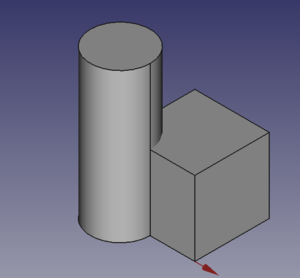
Launch the script with the green arrow and we will see in the 3D view something like:
Placement
Placement Concept is relatively complex, see Aeroplane Tutorial for a more deep explanation.
We usually are in need of placing geometries respect each other, when building complex object this is a recurring task, the most common way is to use the geometry Placement property.
FreeCAD offer a wide choice of ways to set this property, one is more tailored to another depending the knowledge and the background of the user, but the more plain writing is explained in the cited Tutorial, it use a peculiar definition of the Rotation portion of Placement, quite easy to learn.
FreeCAD.Placement(Vector(0,0,0), FreeCAD.Rotation(10,20,30), Vector(0,0,0))
But over other consideration, one thing is crucial, geometry reference point, in other word the point from which the object is modeled by FreeCAD, as described in this table, copied from Placement:
| Object | Reference Point |
|---|---|
| Part.Box | left (minx), front (miny), bottom (minz) vertex |
| Part.Sphere | center of the sphere (ie centre of bounding box) |
| Part.Cylinder | center of the bottom face |
| Part.Cone | center of bottom face (or apex if bottom radius is 0) |
| Part.Torus | center of the torus |
| Features derived from Sketches | the Feature inherits the Position of the underlying Sketch. Sketches always start with Position = (0,0,0). This position corresponds to the origin in the sketch. |
This information has to be kept in mind especially when we have to apply a rotation.
Some examples may help, delete all the line after base_cyl method and insert the portion of code below:
def sfera(nome, rad):
    obj = DOC.addObject("Part::Sphere", nome)
    obj.Radius = rad

    DOC.recompute()

    return obj


def mfuse_obj(nome, objs):
    obj = DOC.addObject("Part::MultiFuse", nome)
    obj.Shapes = objs
    obj.Refine = True
    DOC.recompute()

    return obj


def aeroplano():

    lung_fus = 30
    diam_fus = 5
    ap_alare = lung_fus * 1.75
    larg_ali = 7.5
    spess_ali = 1.5
    alt_imp = diam_fus * 3.0
    pos_ali = (lung_fus*0.70)
    off_ali = (pos_ali - (larg_ali * 0.5))

    obj1 = base_cyl('primo cilindro', 360, diam_fus, lung_fus)

    obj2 = cubo('ali', ap_alare, spess_ali, larg_ali, True, off_ali)

    obj3 = sfera("naso", diam_fus)
    obj3.Placement = FreeCAD.Placement(Vector(0,0,lung_fus), FreeCAD.Rotation(0,0,0), Vector(0,0,0))

    obj4 = cubo('impennaggio', spess_ali, alt_imp, larg_ali, False, 0)
    obj4.Placement = FreeCAD.Placement(Vector(0,alt_imp * -1,0), FreeCAD.Rotation(0,0,0), Vector(0,0,0))

    objs = (obj1, obj2, obj3, obj4)

    obj = mfuse_obj("Forma esempio", objs)
    obj.Placement = FreeCAD.Placement(Vector(0,0,0), FreeCAD.Rotation(0,0,-90), Vector(0,0,pos_ali))

    DOC.recompute()

    return obj

# objects definition

aeroplano()

setview()
Let's explain something in the code:
- We have used a method to define a spehere, using the most easy definition, using only the radius.
- We have introduced a second writing for the 'Union or Fusion, using multiple objects, not more distant from the usual Part::Fuse it uses Part:Multifuse and use only one property
Shapes, we have passed a tuple as arguments, but it accepts also a list. - We have defined a complex object aeroplano (italian word for aeroplane), but we have done it in a "parametric" way, defining some parameters and deriving other parameters, through some calculation, based on the main parameters.
- We have used some Placement
Placementpoperties around in the method and before returning the final geometries we have used aRotationproperty with the Yaw-Pitch-Roll, writing. Note the lastVector(0,0, pos_ali), that define a center of rotation of the whole geometry.
 |
 |
 |
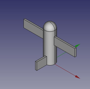
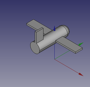
It can be easily noted that aeroplano geometry rotate around his "barycenter" or "center of gravity", that I've fixed at wing center, a place that is relatively "natural", but could be placed wherever you want.
The first Vector(0,0,0) is the Translation vector, not used here, but if you substitute aeroplano() with these lines:
obj_f = aeroplano()

print(obj_F.Placement)
You will se in the Report window this text:
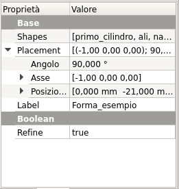
Placement [Pos=(0,-21,21), Yaw-Pitch-Roll=(0,0,-90)]
What has happened?
FreeCAD has translated the Vector(0,0,0), FreeCAD.Rotation(0,0,-90), Vector(0,0,pos_ali) in other word our Placement definition that specifies three components, Translation', Rotation and center of rotation in the "internal" values of only two components, Translation and Rotation.
you can easily visualize the value of pos_ali using a print statement in the aeroplano(... method and see that it is:
pos ali = 21.0
in other word the rotation center of the geometry is at Vector(0,0,21), but this rotation center is not shown in the GUI, it could be entered as a Placement value, it could not be easily retrieved.
This is the meaning of the word "ankward" that I've used to define Placement property.
- FreeCAD scripting: Python, Introduction to Python, Python scripting tutorial, FreeCAD Scripting Basics
- Modules: Builtin modules, Units, Quantity
- Workbenches: Workbench creation, Gui Commands, Commands, Installing more workbenches
- Meshes and Parts: Mesh Scripting, Topological data scripting, Mesh to Part, PythonOCC
- Parametric objects: Scripted objects, Viewproviders (Custom icon in tree view)
- Scenegraph: Coin (Inventor) scenegraph, Pivy
- Graphical interface: Interface creation, Interface creation completely in Python (1, 2, 3, 4, 5), PySide, PySide examples beginner, intermediate, advanced
- Macros: Macros, How to install macros
- Embedding: Embedding FreeCAD, Embedding FreeCADGui
- Other: Expressions, Code snippets, Line drawing function, FreeCAD vector math library (deprecated)
- Hubs: User hub, Power users hub, Developer hub