Robot 6-Axis/sv: Difference between revisions
Emagdalena (talk | contribs) (Created page with "'''Kinematik tabell'''") |
(Updating to match new version of source page) |
||
| (27 intermediate revisions by 3 users not shown) | |||
| Line 1: | Line 1: | ||
| ⚫ | |||
{{TutorialInfo/sv |
|||
|Topic= Robot Workbench |
|||
|Level= Intermediate |
|||
|Time= Unknown |
|||
|Author= |
|||
|FCVersion= |
|||
|Files= |
|||
}} |
|||
==Overview== |
|||
<div class="mw-translate-fuzzy"> |
|||
Denna artikel handlar om hur man hämtar in en standard 6-Axlig industrirobot till FreeCAD för simulering |
Denna artikel handlar om hur man hämtar in en standard 6-Axlig industrirobot till FreeCAD för simulering |
||
</div> |
|||
Beskrivningen följer [http://en.wikipedia.org/wiki/Denavit-Hartenberg_Parameters Denavit-Hartenberg Parameter] systemet, som även beskrivs i John J. Craigs bok "Introduction to Robotics". |
Beskrivningen följer [http://en.wikipedia.org/wiki/Denavit-Hartenberg_Parameters Denavit-Hartenberg Parameter] systemet, som även beskrivs i John J. Craigs bok "Introduction to Robotics". |
||
<span id="Example_Kuka"></span> |
|||
== Exempel Kuka == |
== Exempel Kuka == |
||
| Line 14: | Line 30: | ||
|} |
|} |
||
<span id="Kinematic"></span> |
|||
=== Kinematik === |
=== Kinematik === |
||
| Line 35: | Line 52: | ||
<math>a_{1} = 260 mm </math> |
<math>a_{1} = 260 mm </math> |
||
<math>\alpha_{1} = |
<math>\alpha_{1} = -90</math>° |
||
|| Segment 1 |
|| Segment 1 |
||
| Line 108: | Line 125: | ||
{| class="wikitable" style="color:green; background-color:#ffffcc;" cellpadding="5" cellspacing="0" border="1" |
{| class="wikitable" style="color:green; background-color:#ffffcc;" cellpadding="5" cellspacing="0" border="1" |
||
|+ <div class="mw-translate-fuzzy"> |
|||
'''Kinematik tabell''' |
|||
</div> |
|||
|- |
|- |
||
! <math>i</math> !! <math>\theta</math> !! <math>d</math> !! <math>a</math> !! <math>\alpha</math> |
! <math>i</math> !! <math>\theta</math> !! <math>d</math> !! <math>a</math> !! <math>\alpha</math> |
||
| Line 125: | Line 144: | ||
|} |
|} |
||
Eftersom Kuka robotarna inte har alla axlar i 0 i den ritade L-Positionen, så behöver vi ändra |
|||
axel 2 & 3 med 90°. |
|||
{| class="wikitable" style="color:green; background-color:#ffffcc;" cellpadding="5" cellspacing="0" border="1" |
{| class="wikitable" style="color:green; background-color:#ffffcc;" cellpadding="5" cellspacing="0" border="1" |
||
|+ <div class="mw-translate-fuzzy"> |
|||
'''Kinematik tabell''' |
|||
</div> |
|||
|- |
|- |
||
! <math>i</math> !! <math>\theta</math> !! <math>d</math> !! <math>a</math> !! <math>\alpha</math> |
! <math>i</math> !! <math>\theta</math> !! <math>d</math> !! <math>a</math> !! <math>\alpha</math> |
||
| Line 147: | Line 168: | ||
|} |
|} |
||
I databladet så hittar vi ytterligare information om axlarna: |
|||
[[Image:KukaAxisData.jpg]] |
[[Image:KukaAxisData.jpg]] |
||
Vilket leder till den kompletta tabellen: |
|||
That leads to this complete table: |
|||
{| class="wikitable" style="color:green; background-color:#ffffcc;" cellpadding="5" cellspacing="0" border="1" |
{| class="wikitable" style="color:green; background-color:#ffffcc;" cellpadding="5" cellspacing="0" border="1" |
||
|+ <div class="mw-translate-fuzzy"> |
|||
'''Kinematik tabell''' |
|||
</div> |
|||
|- |
|- |
||
! <math>i</math> !! <math>\theta</math> !! <math>d</math> !! <math>a</math> !! <math>\alpha</math> !! <math>\theta_{min}</math> !! <math>\theta_{max}</math> !! Axis Speed |
! <math>i</math> !! <math>\theta</math> !! <math>d</math> !! <math>a</math> !! <math>\alpha</math> !! <math>\theta_{min}</math> !! <math>\theta_{max}</math> !! Axis Speed |
||
| Line 169: | Line 193: | ||
|} |
|} |
||
<span id="Visual_representation"></span> |
|||
=== |
=== Visuell representation === |
||
FreeCAD kan generera en grov bild ur kinematiktabellen. Men om du vill komma närmare |
|||
FreeCAD can generate a rough visual out of the kinematic table. But if you want closer to reality you can use a VRML file with the robot shape for the simulation. |
|||
verkligheten så kan du använda en VRML fil med robotens utseende för simuleringen. |
|||
T.ex. [http://kuka.com Kuka] handhar VRML filer för sina modeller. |
|||
The VRML file gets loaded while the creation of the specific robot in FreeCAD. In order to allow FreeCAD to move the axis we have to edit the VRML file and insert special transformation nodes FreeCAD can find and manipulate. |
|||
VRML filen laddas under skapandet av den specifika roboten |
|||
i FreeCAD. För att FreeCAD ska kunna röra axlarna så måste vi redigera |
|||
VRML filen och sätta in speciella omvandlingsnoder som FreeCAD kan hitta |
|||
och manipulera. |
|||
Detta visas återigen med exemplet Kuka KR 16. |
|||
med start från rad 1: |
|||
Beginning from line 1: |
|||
#VRML V2.0 utf8 |
#VRML V2.0 utf8 |
||
| Line 201: | Line 230: | ||
[ |
[ |
||
... |
... |
||
Du ser att denna fil är exporterad med en robotsimuleringsmjukvara som kallas för Tecnomatix. Ta bort denna notis och skriv in en URL var du fick denna fil ifrån, därför att Tecnomatix har ingen upphovsrätt på filinnehållet. Det är endast en omvandlare! Först av allt så tar vi bort '''Background''' noden. Ta sedan bort '''rotation''' och '''scale''' noden för att få modellen i mm och uppåtpekande Z. |
|||
Aldeles vid slutet: |
|||
Right at the end: |
|||
] } |
] } |
||
] } |
] } |
||
| Line 221: | Line 250: | ||
#} |
#} |
||
Kommentera bort '''TimeSensor''' och de 6 rutterna. Dessa 6 rader ger dig ett tips på var robotens axlar är någonstans! |
|||
Sök först efter "AXIS_04_OBJ" som tar dig till den platsen: |
|||
... |
... |
||
Transform { rotation 1 0 0 1.570796 children [ |
Transform { rotation 1 0 0 1.570796 children [ |
||
| Line 244: | Line 274: | ||
[ |
[ |
||
... |
... |
||
Du måste precis innan definitionen av denna nod sätta in raden '''"DEF FREECAD_AXIS1 Transform { rotation 0 1 0 0 children ["''' vilket är FreeCADs ankare för att förflytta axeln. |
|||
Gör nu detsamma för '''FREECAD_AXIS2''','''FREECAD_AXIS3''','''FREECAD_AXIS4''','''FREECAD_AXIS5''' och '''FREECAD_AXIS6'''. |
|||
Glöm inte de stängande parenteserna vid slutet av filen, och du är färdig! |
|||
Don't forget the closing brackets at the end of the file and you're done! |
|||
Du kan ladda VRML:en genom att exemplifiera roboten: |
|||
You can load the VRML by instantiating the robot: |
|||
App.activeDocument().addObject("Robot::RobotObject","Robot") |
App.activeDocument().addObject("Robot::RobotObject","Robot") |
||
App.activeDocument().Robot.RobotVrmlFile = "C:/_Projekte/FreeCAD0.9_build/mod/Robot/Lib/Kuka/kr16.wrl" |
App.activeDocument().Robot.RobotVrmlFile = "C:/_Projekte/FreeCAD0.9_build/mod/Robot/Lib/Kuka/kr16.wrl" |
||
vilket ska ge dig detta resultat: |
|||
which should give you that result: |
|||
[[Image:KukaKR16FreeCAD.jpg]] |
[[Image:KukaKR16FreeCAD.jpg]] |
||
| Line 260: | Line 290: | ||
{| class="wikitable" style="color:green; background-color:#ffffcc;" cellpadding="5" cellspacing="0" border="1" |
{| class="wikitable" style="color:green; background-color:#ffffcc;" cellpadding="5" cellspacing="0" border="1" |
||
|+ <div class="mw-translate-fuzzy"> |
|||
'''Kinematik tabell''' |
|||
</div> |
|||
|- |
|- |
||
! <math>i</math> !! <math>\theta</math> !! <math>d</math> !! <math>a</math> !! <math>\alpha</math> !! <math>\theta_{min}</math> !! <math>\theta_{max}</math> !! Axis Speed |
! <math>i</math> !! <math>\theta</math> !! <math>d</math> !! <math>a</math> !! <math>\alpha</math> !! <math>\theta_{min}</math> !! <math>\theta_{max}</math> !! Axis Speed |
||
| Line 283: | Line 315: | ||
{| class="wikitable" style="color:green; background-color:#ffffcc;" cellpadding="5" cellspacing="0" border="1" |
{| class="wikitable" style="color:green; background-color:#ffffcc;" cellpadding="5" cellspacing="0" border="1" |
||
|+ <div class="mw-translate-fuzzy"> |
|||
'''Kinematik tabell''' |
|||
</div> |
|||
|- |
|- |
||
! <math>i</math> !! <math>\theta</math> !! <math>d</math> !! <math>a</math> !! <math>\alpha</math> !! <math>\theta_{min}</math> !! <math>\theta_{max}</math> !! Axis Speed |
! <math>i</math> !! <math>\theta</math> !! <math>d</math> !! <math>a</math> !! <math>\alpha</math> !! <math>\theta_{min}</math> !! <math>\theta_{max}</math> !! Axis Speed |
||
| Line 300: | Line 334: | ||
|} |
|} |
||
=== Links === |
|||
[[Category:User Documentation]] |
|||
| ⚫ | |||
* [https://link.springer.com/referenceworkentry/10.1007%2F978-3-540-30301-5_2 Springer Handbook of Robotics, section Kinematics, p 9-33]. |
|||
* [https://www.youtube.com/watch?v=qZB3_gKBwf8 Denavit-Hartenberg Parameter 3D Video Tutorial] Denavit-Hartenberg Parameter 3D Video Tutorial for a KUKA industry robot on YouTube (german). |
|||
* [https://www.youtube.com/watch?v=rA9tm0gTln8 Denavit-Hartenberg Reference Frame Layout] Denavit-Hartenberg Reference Frame Layout on YouTube. |
|||
* [http://www.roboanalyzer.com/ RoboAnalyzer] RoboAnalyzer is a 3D model based software that can be used to teach and learn the Robotics concepts. |
|||
{{Robot_Tools_navi{{#translation:}}}} |
|||
{{Userdocnavi{{#translation:}}}} |
|||
Latest revision as of 12:56, 14 April 2023
| Topic |
|---|
| Robot Workbench |
| Level |
| Intermediate |
| Time to complete |
| Unknown |
| Authors |
| FreeCAD version |
| Example files |
| See also |
| None |
Overview
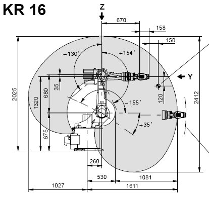
Denna artikel handlar om hur man hämtar in en standard 6-Axlig industrirobot till FreeCAD för simulering
Beskrivningen följer Denavit-Hartenberg Parameter systemet, som även beskrivs i John J. Craigs bok "Introduction to Robotics".
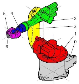
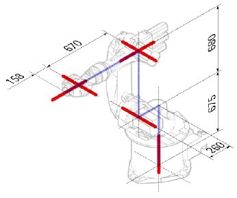
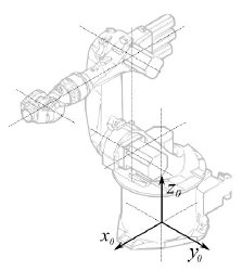
Exempel Kuka
|
|
|
Kinematik
| Segment | Parameter | Beskrivning |
|---|---|---|
|
Basens konfiguration | |
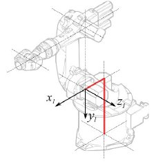
|
° |
Segment 1 |
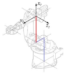
|
°
° |
Segment 2 |
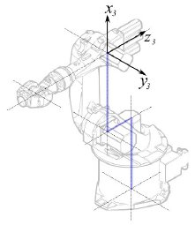
|
° |
Segment 3 |
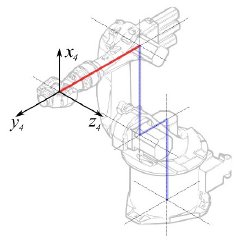
|
° |
Segment 4 |
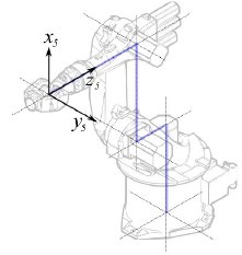
|
° |
Segment 5 |
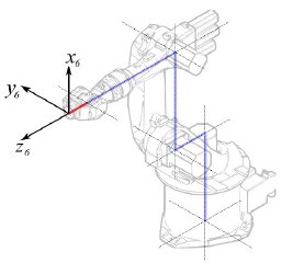
|
° |
Segment 6 |
Detta leder till följande tabell:
| 1 | q1 | 675 mm | 260 mm | -90° |
| 2 | q2 - 90° | 0 mm | 680 mm | 0° |
| 3 | q3 | 0 mm | 0 mm | 90° |
| 4 | q4 | -670 mm | 0 mm | -90° |
| 5 | q5 | 0 mm | 0 mm | 90° |
| 6 | q6 | -158 mm | 0 mm | 180° |
Eftersom Kuka robotarna inte har alla axlar i 0 i den ritade L-Positionen, så behöver vi ändra axel 2 & 3 med 90°.
| 1 | q1 | 675 mm | 260 mm | -90° |
| 2 | q2 | 0 mm | 680 mm | 0° |
| 3 | q3 - 90° | 0 mm | 0 mm | 90° |
| 4 | q4 | -670 mm | 0 mm | -90° |
| 5 | q5 | 0 mm | 0 mm | 90° |
| 6 | q6 | -158 mm | 0 mm | 180° |
I databladet så hittar vi ytterligare information om axlarna:
Vilket leder till den kompletta tabellen:
| Axis Speed | |||||||
|---|---|---|---|---|---|---|---|
| 1 | 0 | 675 | 260 | -90 | -185 | 185 | 156 |
| 2 | 0 | 0 | 680 | 0 | -155 | 35 | 156 |
| 3 | - 90 | 0 | 0 | 90 | -130 | 154 | 156 |
| 4 | 0 | -670 | 0 | -90 | -350 | 350 | 330 |
| 5 | 0 | 0 | 0 | 90 | -130 | 130 | 330 |
| 6 | 0 | -158 | 0 | 180 | -350 | 350 | 615 |
Visuell representation
FreeCAD kan generera en grov bild ur kinematiktabellen. Men om du vill komma närmare verkligheten så kan du använda en VRML fil med robotens utseende för simuleringen. T.ex. Kuka handhar VRML filer för sina modeller. VRML filen laddas under skapandet av den specifika roboten i FreeCAD. För att FreeCAD ska kunna röra axlarna så måste vi redigera VRML filen och sätta in speciella omvandlingsnoder som FreeCAD kan hitta och manipulera.
Detta visas återigen med exemplet Kuka KR 16. med start från rad 1:
#VRML V2.0 utf8
#
# This VRML97 file was exported using eM-Workplace
# (c) Tecnomatix Technologies GmbH & Co. KG
#     Heisenberg-Bogen 1
#     D-85609 Aschheim-Dornach
#     GERMANY
#
#Background
#{
#   skyColor   [0.752941 0.752941 0.752941]
#}
Transform
{
   #rotation 1 0 0 -1.5707963
   #scale .001 .001 .001
   children
   [
           DEF AOBJ_0001_000_TRAFO Transform
           {
              children
              [
...
Du ser att denna fil är exporterad med en robotsimuleringsmjukvara som kallas för Tecnomatix. Ta bort denna notis och skriv in en URL var du fick denna fil ifrån, därför att Tecnomatix har ingen upphovsrätt på filinnehållet. Det är endast en omvandlare! Först av allt så tar vi bort Background noden. Ta sedan bort rotation och scale noden för att få modellen i mm och uppåtpekande Z.
Aldeles vid slutet:
  ] }
  ] }
  ] }
  ]
}
#ROUTE SENS_04_OBJ.rotation_changed TO AXIS_04_OBJ.rotation
#ROUTE SENS_27_OBJ.rotation_changed TO AXIS_27_OBJ.rotation
#ROUTE SENS_32_OBJ.rotation_changed TO AXIS_32_OBJ.rotation
#ROUTE SENS_44_OBJ.rotation_changed TO AXIS_44_OBJ.rotation
#ROUTE SENS_46_OBJ.rotation_changed TO AXIS_46_OBJ.rotation
#ROUTE SENS_49_OBJ.rotation_changed TO AXIS_49_OBJ.rotation
#DEF AnySIMTimer TimeSensor
#{
#   cycleInterval 1.000000
#   loop          TRUE
#}
Kommentera bort TimeSensor och de 6 rutterna. Dessa 6 rader ger dig ett tips på var robotens axlar är någonstans! Sök först efter "AXIS_04_OBJ" som tar dig till den platsen:
...
    Transform { rotation 1 0 0 1.570796 children [
        DEF SENS_04_OBJ-0001 CylinderSensor
        {
           diskAngle 1.570796
           minAngle  -3.228859
           maxAngle  3.228859
           offset    0.000000
        }
      DEF FREECAD_AXIS1 Transform { rotation 0 1 0 0 children [
      DEF AXIS_04_OBJ-0001 Transform
     {
        children
        [
        Transform { rotation 1 0 0 -1.570796 children [
           DEF AOBJ_0001_003_TRAFO Transform
           {
              rotation 1.000000 0.000000 0.000000 3.141593
              translation -600.000000 500.000000 300.000000
              children
              [
...
Du måste precis innan definitionen av denna nod sätta in raden "DEF FREECAD_AXIS1 Transform { rotation 0 1 0 0 children [" vilket är FreeCADs ankare för att förflytta axeln.
Gör nu detsamma för FREECAD_AXIS2,FREECAD_AXIS3,FREECAD_AXIS4,FREECAD_AXIS5 och FREECAD_AXIS6. Glöm inte de stängande parenteserna vid slutet av filen, och du är färdig!
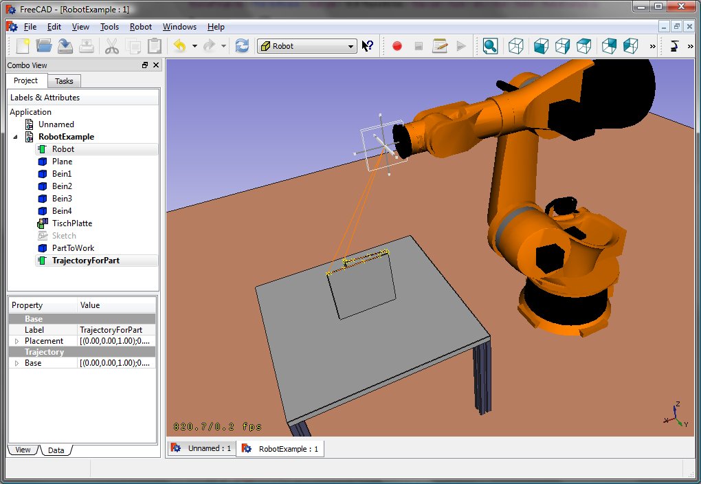
Du kan ladda VRML:en genom att exemplifiera roboten:
App.activeDocument().addObject("Robot::RobotObject","Robot")
App.activeDocument().Robot.RobotVrmlFile = "C:/_Projekte/FreeCAD0.9_build/mod/Robot/Lib/Kuka/kr16.wrl"
vilket ska ge dig detta resultat:
KR 210
| Axis Speed | |||||||
|---|---|---|---|---|---|---|---|
| 1 | 0 | 750 | 350 | -90 | -185 | 185 | 156 |
| 2 | 0 | 0 | 1250 | 0 | -155 | 35 | 156 |
| 3 | - 90 | 0 | 0 | 90 | -130 | 154 | 156 |
| 4 | 0 | -1100 | 0 | -90 | -350 | 350 | 330 |
| 5 | 0 | 0 | 0 | 90 | -130 | 130 | 330 |
| 6 | 0 | -230 | 0 | 180 | -350 | 350 | 615 |
KR 500
| Axis Speed | |||||||
|---|---|---|---|---|---|---|---|
| 1 | 0 | 1045 | 500 | -90 | -185 | 185 | 156 |
| 2 | 0 | 0 | 1300 | 0 | -155 | 35 | 156 |
| 3 | - 90 | 0 | 0 | 90 | -130 | 154 | 156 |
| 4 | 0 | -1025 | 0 | -90 | -350 | 350 | 330 |
| 5 | 0 | 0 | 0 | 90 | -130 | 130 | 330 |
| 6 | 0 | -250 | 0 | 180 | -350 | 350 | 615 |
Links
- Springer Handbook of Robotics, section Kinematics, p 9-33.
- Denavit-Hartenberg Parameter 3D Video Tutorial Denavit-Hartenberg Parameter 3D Video Tutorial for a KUKA industry robot on YouTube (german).
- Denavit-Hartenberg Reference Frame Layout Denavit-Hartenberg Reference Frame Layout on YouTube.
- RoboAnalyzer RoboAnalyzer is a 3D model based software that can be used to teach and learn the Robotics concepts.
- Trajectories, non parametric: Create a trajectory, Set default orientation, Set default values, Insert waypoint, Insert waypoint (mouse)
- Trajectories, parametric: Create a trajectory from edges, Dress-up trajectory, Trajectory compound
- Getting started
- Installation: Download, Windows, Linux, Mac, Additional components, Docker, AppImage, Ubuntu Snap
- Basics: About FreeCAD, Interface, Mouse navigation, Selection methods, Object name, Preferences, Workbenches, Document structure, Properties, Help FreeCAD, Donate
- Help: Tutorials, Video tutorials
- Workbenches: Std Base, Arch, Assembly, CAM, Draft, FEM, Inspection, Mesh, OpenSCAD, Part, PartDesign, Points, Reverse Engineering, Robot, Sketcher, Spreadsheet, Surface, TechDraw, Test Framework
- Hubs: User hub, Power users hub, Developer hub


