PartDesign tutorial/pl: Difference between revisions
(Created page with "# Przełącz się do środowiska produkcyjnego Projekt Części. # Z zaznaczonym szkicem w oknie widoku drzewa, naciśnij przycisk {{Button|File:PartDesign_...") |
(Created page with "Innym sposobem na tworzenie geometrii 3D jest narzędzie 32px Wyciągnij wybrany szkic przez obrót.") |
||
| Line 31: | Line 31: | ||
# Naciśnij przycisk {{Button|OK}}. |
# Naciśnij przycisk {{Button|OK}}. |
||
Innym sposobem na tworzenie geometrii 3D jest narzędzie [[Image:PartDesign_Revolution.svg|32px]] [[PartDesign_Revolution/pl|Wyciągnij wybrany szkic przez obrót]]. |
|||
[[Image:PartDesign_revolution_exercise.png|480px]] |
[[Image:PartDesign_revolution_exercise.png|480px]] |
||
Revision as of 05:18, 15 August 2021
| Temat |
|---|
| Szkicowanie |
| Poziom trudności |
| Początkujący |
| Czas wykonania |
| 15 minut |
| Autorzy |
| Drei |
| Wersja FreeCAD |
| 0.16 lub nowszy |
| Pliki z przykładami |
| Nie dołączono |
| Zobacz również |
| - |
Wprowadzenie
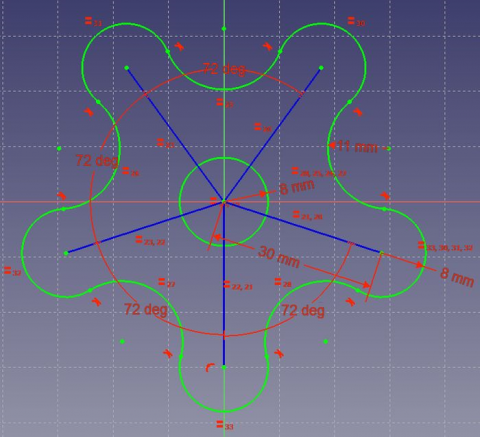
Ten poradnik ma na celu zapoznanie czytelnika z podstawowym przepływem pracy w środowisku pracy Projekt Części. Czytelnik zobaczy jak tworzyć obiekty 3D na podstawie szkiców, wykonywać operacje odejmowania oraz jak powielać określone cechy we wzorze.
Wymagania
- FreeCAD w wersji v0.17 lub wyższej.
- Czytelnik ukończył poradnik Podstawy dla środowiska pracy Szkicownik
Procedura
Tworzenie geometrii 3D
Celem środowiska roboczego Projekt Części jest umożliwienie użytkownikowi tworzenia geometrii w przestrzeni 3D. W związku z tym jest ono wyposażone w narzędzia do wykorzystania szkiców i przekształcania ich w obiekty 3D.
Aby to osiągnąć, istnieją dwa narzędzia: Wyciągnij oraz
Wyciągnij przez obrót. Obok ich subtraktywnych odpowiedników (
kieszeń i
rowek) tworzą większość typowych akcji używanych przez to środowisko pracy.
- Przełącz się do środowiska produkcyjnego Projekt Części.
- Z zaznaczonym szkicem w oknie widoku drzewa, naciśnij przycisk
Zawartość, wybierz domyślną płaszczyznę XY i naciśnij przycisk OK. Szkic powinien pojawić się teraz wewnątrz zawartości.
- Wybierz
Wyciągnij wybrany szkic.
- Ustaw odległość na 5 mm.
- Naciśnij przycisk OK.
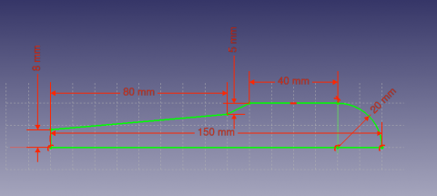
Innym sposobem na tworzenie geometrii 3D jest narzędzie Wyciągnij wybrany szkic przez obrót.
- Create a new body
PartDesign Body, and then a sketch based on the image above.
- The sketch can be on any plane, but should be co-incident with the horizontal axis.
- Select
Revolution
- Set the "Axis" to the "Horizontal Sketch Axis"
- Set the angle to 360°
Subtracting Features
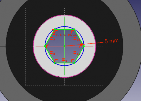
We'll begin by creating a sketch with the shape we want to subtract.
- Select the top flat face of the "Revolution"
- Select
New sketch
- Select
External Geometry
- Approach the edge of the pad. An arc should be highlighted
- Select the arc. An arc of a different color should appear in the sketch
- Create a hexagon centered on the same point as the arc and set the radius of the reference circle to 5 mm
When a 3D element has been created it is possible to create references to it within a sketch.
- Select
External Geometry.
- Approach the element that you wish to reference, the edge of a Pad for example.
- Click on it
- New elements of a different color should appear on the sketch in the location of the feature you wish to reference.
Afterwards, we'll proceed to apply a Pocket feature.
- Select the sketch
- Select
Pocket
- Set the distance to Through all
Pattern Features
Recall the extruded profile that was created at the start of the tutorial.
- Select the top face of the object
- Create a new Sketch
- Create reference geometry linked to the top arm of the figure
- Create a circle constrained to the center of the reference arc
- Set its radius to 3 mm
- Pocket the sketch through all the workpiece
Instead of creating a circle for each hole in the sketch, we will introduce the concept of Pattern Features. These tools operate by replicating a feature in the workpiece that has already been created and that we wish to reproduce in a linear or circular arrangement. We will use a combination of Linear and Polar pattern features simulatneously to obtain the final workpiece.
- Select the Pocket feature that we just created in the Tree View
- Select
MultiTransform
In the Combo View we are now asked to introduce the Transformations that we desire. Notice that in the MultiTransform parameters menu we see that FreeCAD has identified the Pocket as the Original feature and a second box requests us to Right click it to introduce the pattern features.
- Right click the box
- Select Add Linear Pattern
- Set the Direction to Vertical Sketch Axis
- Set length to 10 mm
- Leave occurrences at 2
- Click OK
- Right click the box again to add a Polar Pattern. Notice that the 3D view has now added the linear pattern.
- Set occurrences to 5
- Click OK twice
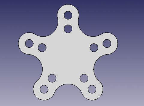
Po wykonaniu tego zadania powinieneś mieć następujący wynik.
Jeśli nie, edytuj ponownie operację Transformacja wielokrotna, klikając na niej dwukrotnie w widoku drzewa. Sprawdź obie cechy wzoru, aby wykryć konieczne modyfikacje, takie jak Oś oraz czy Kierunek musi zostać odwrócony.
Zakończyliśmy teraz prezentacje podstawowego przepływu pracy dla środowiska Projekt Części.


