PartDesign Beispiele
Diese Dokumentation ist noch nicht fertiggestellt. Bitte hilf mit und trage etwas zur Dokumentation bei.
Die Seite GuiBefehl Modell erklärt, wie Befehle dokumentiert werden sollten. Unter Category:UnfinishedDocu findest du weitere unvollständige Seiten wie diese (und unter Category:UnfinishedDocu/de unvollständige Übersetzungen). Siehe Category:Command Reference für sämtliche Befehle (und Category:UnfinishedDocu/de für vorhandene Übersetzungen).
Siehe WikiSeiten, um zu lernen, wie die Wiki-Seiten bearbeitet werden und FreeCAD Unterstützen, um andere Wege zu entdecken, wie du einen Beitrag leisten kannst.
Einführung
Manchmal braucht man einen Hinweis darauf, wie mächtig ein Werkzeug ist, ohne zu viele Erklärungen.
Dies ist eine Sammlung von Beispielen, die mit bestimmten Werkzeugen erzielt werden können. Detaillierte Erklärungen findet man bei den Werkzeugbeschreibungen und in Tutorien, die man im Web findet.
Pad
PartDesign Pad Ist ein Werkzeug, zum Erstellen von Pad-Objekten, die prismatische Objekte sind, wie z. B. Extrusionsobjekte, Zylinder, Kegel, Würfel, Keile...
Jedes Objekt basiert auf einer Kontur (gelb), die die Querschnittsform definiert (vorzugsweise mit dem Arbeitsbereich Sketcher erstellt).
Die Kontur wird entlang einer Richtung gezogen (ausgetragen, extrudiert), um ein Objekt mit einer Dicke oder einer Länge zu versehen.
Standardmäßig wird die Normalenrichtung der Ebene verwendet, die die Kontur enthält (Skizzenebene). Wahlweise kann die Richtung durch Bearbeiten der Parameter im Eigenschafteneditor geändert werden oder durch das Anwählen einer separaten geraden Linie (weiß).
Gallerie
Prismatic Primitives
| Cylinder | 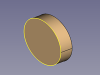
|
|
| Cube | 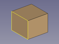
|
|
| Cuboid | 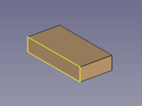
|
|
| Regular Prism | 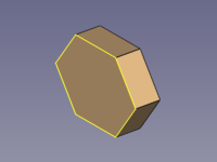
|
|
| Wedge | 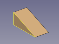
|
|
Prismatic Profiles
Additive Pipe
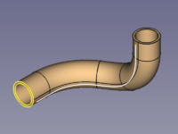
PartDesign Additive pipe is a tool to create AdditivePipe objects such as sweep objects, extrusion objects, rotation objects, cylinders, cones, cubes, pyramids, spheres...
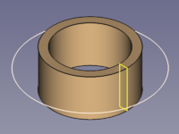
Each object is based on at least two lines (preferably made with the Sketcher Workbench):
- One outline (yellow), to define the cross-section shape.
- One path (white), to sweep along.
It is not hard to realize that some objects can be created with other tools too, but would you have guessed how versatile this tool is without these examples?
Gallery
Circular Sweep Objects
| Sphere | 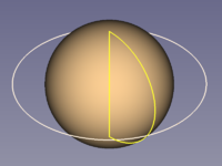
|
|
| Sphere Segment | 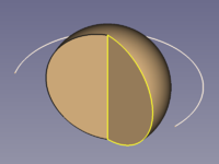
|
|
| Hemisphere | 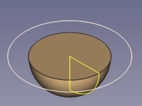
|
|
| Torus | 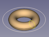
|
|
| Cone | 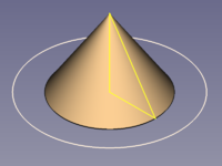
|
|
| Cylinder | 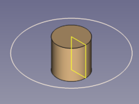
|
|
| Pipe Hollow Cylinder |
|
|
Prismatic Objects
Straight Sweep Objects
| Cylinder | 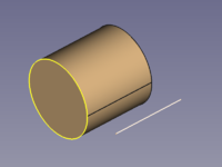
|
|
| Cube | 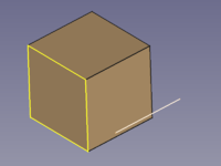
|
|
| Cuboid | 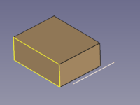
|
|
| Wedge | 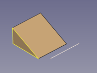
|
|
| Regular Prism | 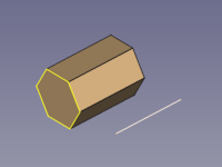
|
|
| Star-shaped Prism | 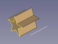
|
|
| Double-T Beam | 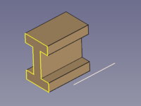
|
|
Conical Objects
| Cone | 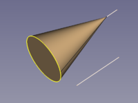
|
|
| Pyramid | 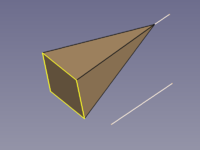
|
|
| Tilted Pyramid | 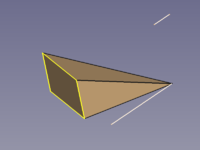
|
|
Curved Sweep Objects
| Hose (Pipe) |
|
|
| Square Pipe | 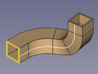
|
|
| Wire | 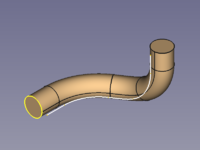
|
|
| Horn | 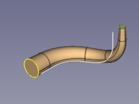
|
|
| Legendary Hex-Wrench |
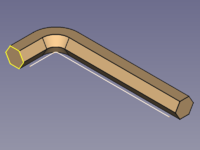
|
|
Spiral and Helical Objects
| Coil Spring | 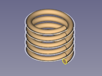
|
|
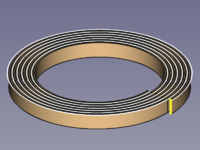
| Hairspring Balance Spring |
|
|
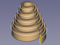
| Volute Spring, Conical Spring |
|
|
Transition Objects
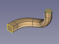
| Square to Circle via path |
|
|
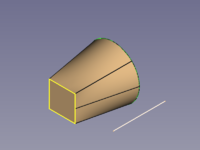
| Square to Circle direct |
|
|
| Polygon to Star | 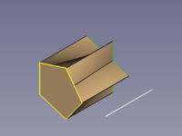
|
|
Options
Corner Transition
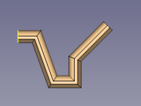
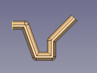
A polyline can be used as a path, and the property Transition influences the shapes of the corners.
Transformed needs special attention as it can produce flat areas where the thickness is 0.
| Parameter | Iso View | Top View |
|---|---|---|
| Transformed | 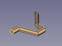
|
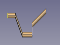
|
| Right corner | 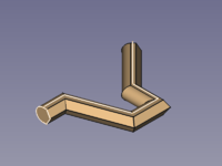
|
|
| Round corner | 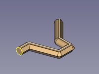
|
|
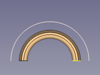
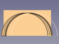
Orientation Mode
| Parameter | Iso View | Top View |
|---|---|---|
| Standard | 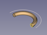
|
|
| Fixed | 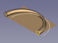
|
|
| Frenet | 
|

|
| Auxiliary | ||
| Binormal |