Manual:Creating FEM analyses/fr: Difference between revisions
(Created page with "=== Préparation de la géométrie ===") |
(Created page with "Nous allons commencer avec la maison que nous avons modélisée dans le chapitre de modélisation BIM (BIM modeling). Cependant, certains changements d...") |
||
| Line 13: | Line 13: | ||
=== Préparation de la géométrie === |
=== Préparation de la géométrie === |
||
Nous allons commencer avec la maison que nous avons modélisée dans le chapitre de modélisation BIM ([[Manual:BIM modeling|BIM modeling]]). Cependant, certains changements doivent être apportés pour rendre le modèle adapté aux calculs FEM. Cela implique essentiellement de rejeter les objets que nous ne voulons pas inclure dans le calcul, comme la porte et la fenêtre, et de joindre tous les objets restants en un seul. |
|||
We will start with the house we modelled in the [[Manual:BIM modeling|BIM modeling]] chapter. However, some changes have to be made to make the model suitable for FEM calculations. This involves, basically, discarding the objects that we don't want to include in the calculation, such as the door and window, and joining all the remaining objects into one. |
|||
* Load the [https://github.com/yorikvanhavre/FreeCAD-manual/blob/master/files/house.FCStd house model] we modeled earlier |
* Load the [https://github.com/yorikvanhavre/FreeCAD-manual/blob/master/files/house.FCStd house model] we modeled earlier |
||
Revision as of 18:28, 5 June 2017
- Introduction
- Découvrir FreeCAD
- Travailler avec FreeCAD
- Tous les ateliers en un coup d'œil
- Modélisation traditionnelle, mode CSG
- Dessin 2D traditionnel
- Modélisation pour la conception de produits
- Préparation de modèles pour l'impression 3D
- Génération de dessins 2D
- Modélisation BIM
- Utilisation de feuilles de calcul
- Création d'analyses FEM
- Création de rendus réalistes
- Programmation Python
- La communauté
FEM signifie Méthode des éléments finis (Finite Element Method). Il s'agit d'un vaste sujet mathématique, mais dans FreeCAD, nous pouvons résumer cela comme moyen de calculer les propagations à l'intérieur d'un objet 3D, en le coupant en petits morceaux et en analysant l'impact de chaque petit morceau sur ses voisins. Cela a plusieurs utilisations dans les domaines de l'ingénierie et de l'électromagnétisme, mais nous examinerons plus en profondeur une seule utilisation déjà développée dans FreeCAD, qui simule des déformations dans des objets soumis à des forces et à des poids.
L'obtention de cette simulation se fait dans FreeCAD avec l’atelier FEM (FEM Workbench). Cela implique différentes étapes : Préparer la géométrie, définir son matériau, effectuer le maillage, diviser en parties plus petites, comme nous l'avons fait dans le chapitre Préparer les objets pour l’impression 3D (Preparing objects for 3D printing), et finalement calculer la simulation.
Préparation de FreeCAD
La simulation elle-même est réalisée par un autre logiciel, utilisé par FreeCAD pour obtenir les résultats. Comme il existe plusieurs applications de simulation FEM intéressantes disponibles, l’atelier FEM (FEM Workbench) a été conçu pour pouvoir en utiliser plus d'une. Cependant, actuellement, seul CalculiX est entièrement implémenté. Un autre logiciel, appelé NetGen, qui est responsable de la génération du maillage de subdivision, est également nécessaire. Des instructions détaillées pour installer ces deux composants sont fournies dans la documentation FreeCAD (FreeCAD documentation).
Préparation de la géométrie
Nous allons commencer avec la maison que nous avons modélisée dans le chapitre de modélisation BIM (BIM modeling). Cependant, certains changements doivent être apportés pour rendre le modèle adapté aux calculs FEM. Cela implique essentiellement de rejeter les objets que nous ne voulons pas inclure dans le calcul, comme la porte et la fenêtre, et de joindre tous les objets restants en un seul.
- Load the house model we modeled earlier
- Delete or hide the page object, the section planes and the dimensions, so we stay only with our model
- Hide the window, the door and the ground slab
- Also hide the metal beams from the roof. Since they are very different objects from the rest of the house, we will simplify our calculation by not including it. Instead, we will consider that the roof slab is directly placed on top of the wall.
- Now move the roof slab down so it rests on top of the wall: Edit the Rectangle object that we used as a base of the roof slab, and change it's Placement->Position->X value from 3.18m to 3.00m
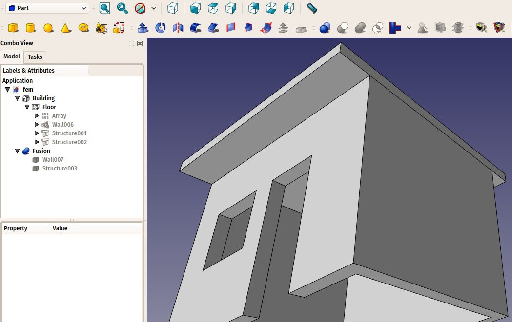
- Our model is now clean:
- The FEM Workbench can currently calculate deformations on one single object only. Therefore, we need to join our two objects (the wall and the slab). Switch to the Part Workbench, select the two objects, and press the
 Union. We now have obtained one fused object:
Creating the analysis
- We are now ready to start a FEM analysis. Let's switch to the FEM Workbench
- Select the fusion object
- Press the
 New Analysis button
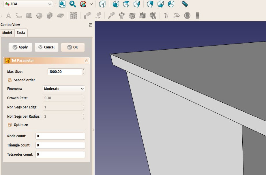
 - A new analysis will be created and a settings panels opened. Here you can define the meshing parameters to be used to produce the FEM mesh. The main setting to edit is the Max Size which defines the maximum size (in millimeters) of each piece of the mesh. For now, we can leave the default value of 1000:
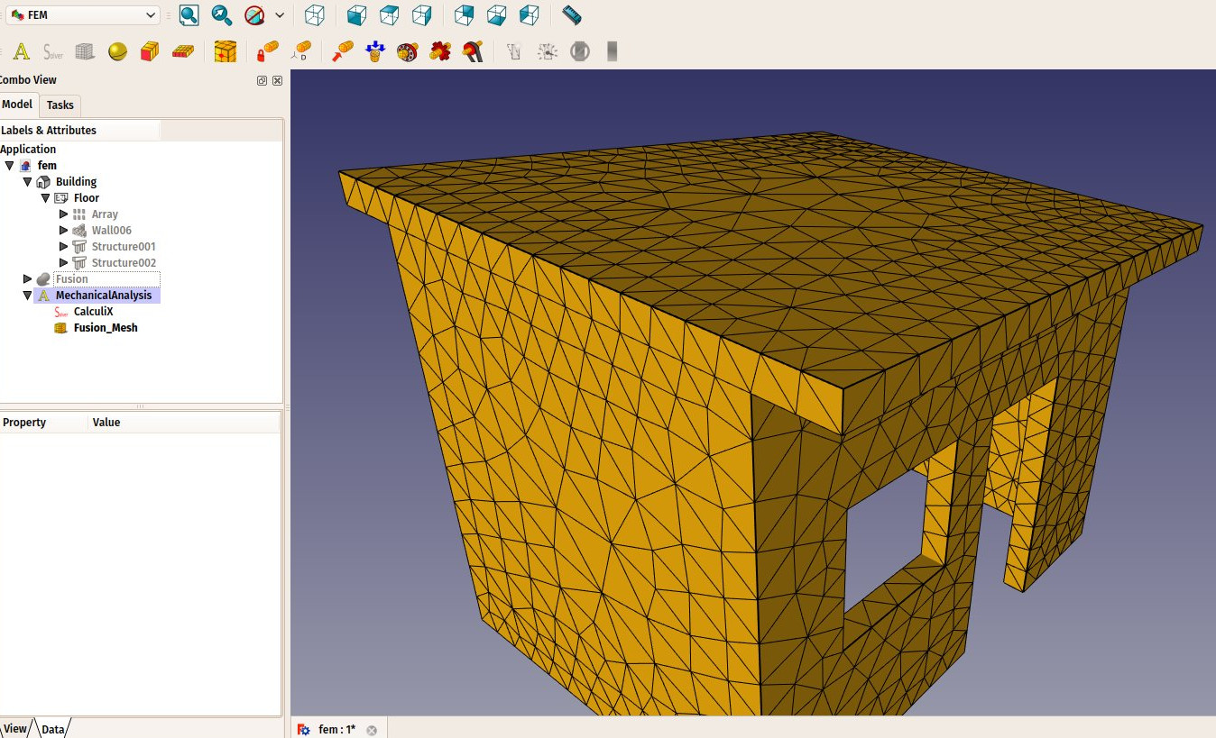
- After pressing OK and a few seconds of calculation, our FEM mesh is now ready:
- We can now define the material to be applied to our mesh. This is important because depending on the material strength, our object will react differently to forces applied to it. Select the analysis object, and press the
 New Material button.
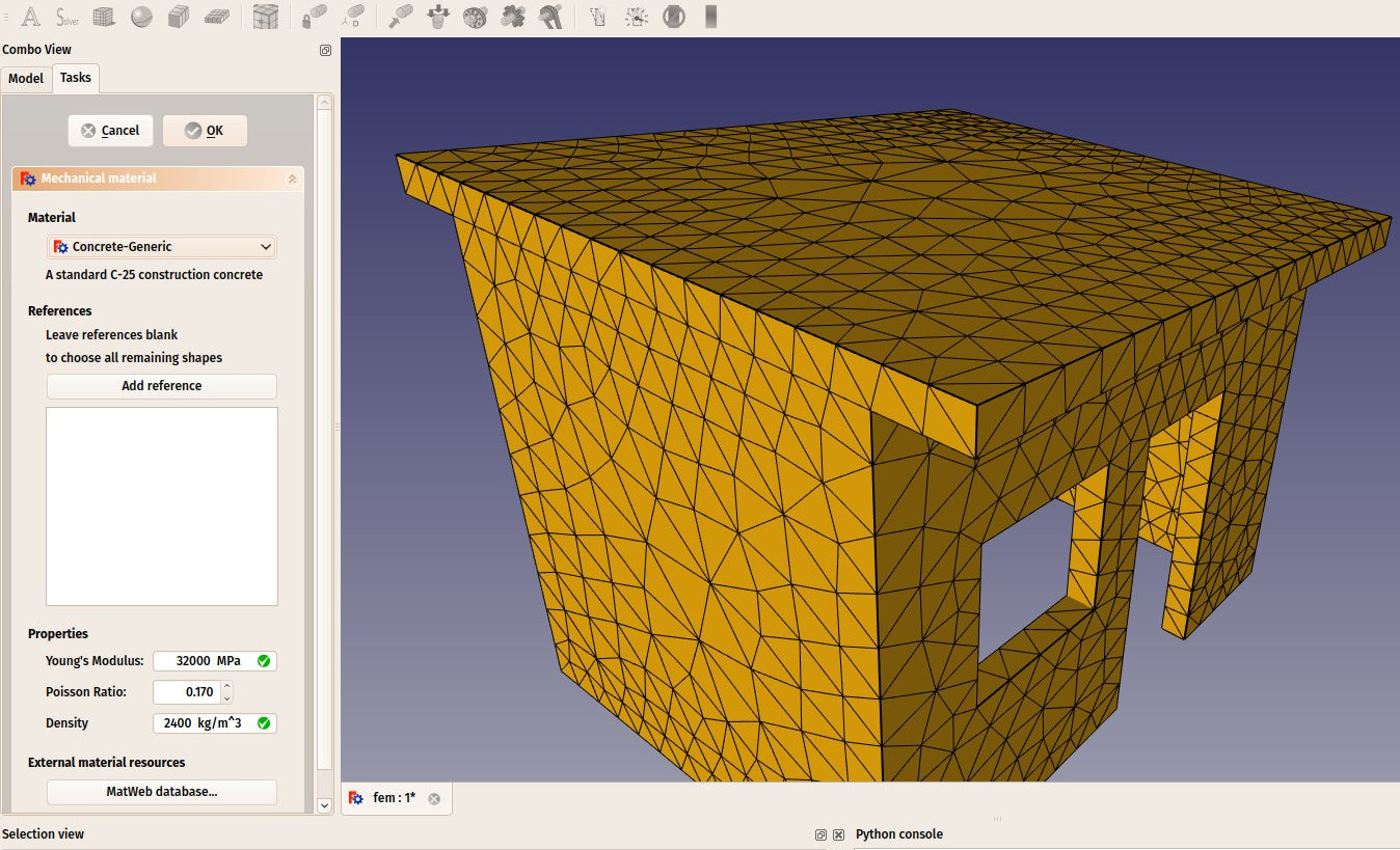
 - A task panel will open to allow us to choose a material. In the Material drop-down list, choose the Concrete-generic material, and press OK.
- We are now ready to apply forces. Let's start by specifying which faces are fixed into the ground and can therefore not move. Press the
 Constraint fixed button.
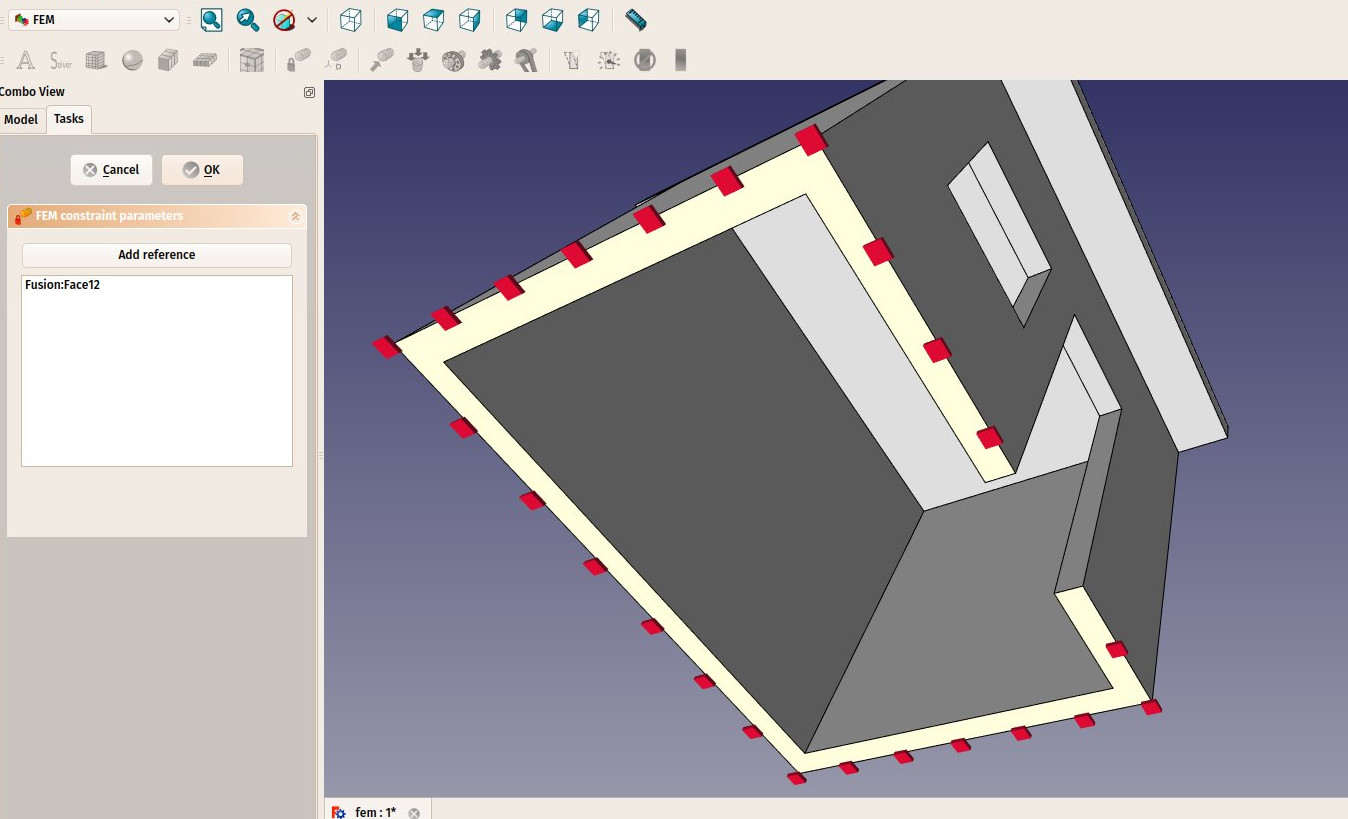
 - Click on the bottom face of our building and press OK. The bottom face is now indicated as unmovable:
- We will now add a load on the top face, that could represent, for example, a massive weight being spread on the roof. For this we will use a pressure constraint. Press the
 Constraint pressure button.
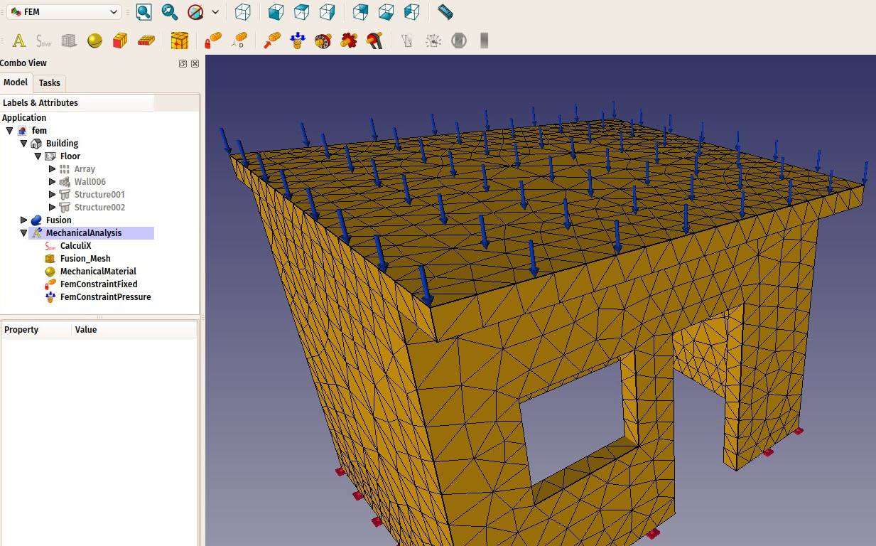
 - Click the top face of the roof, set the pressure to 10MPa (the pressure is applied by square millimeter) and click the OK button. Our force is now applied:
- We are now ready to start the calculation. Select the CalculiX object in the tree view, and press the
 Start Calculation button.
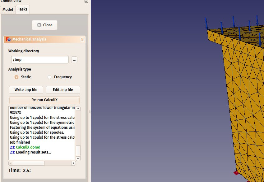
 - In the task panel that will open, click first the Write .inp file button to create the input file for CalculiX, then the Run CalculiX button. A few moments later, the calculation will be done:
- We can now look at the results. Close the task panel, and see that a new Results object has been added to our analysis.
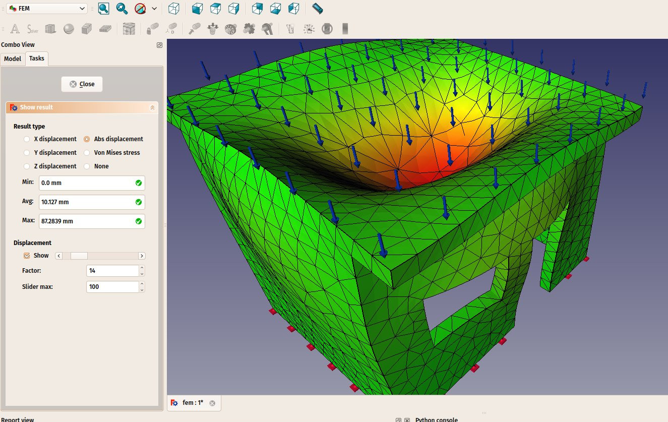
- Double-click the Results object
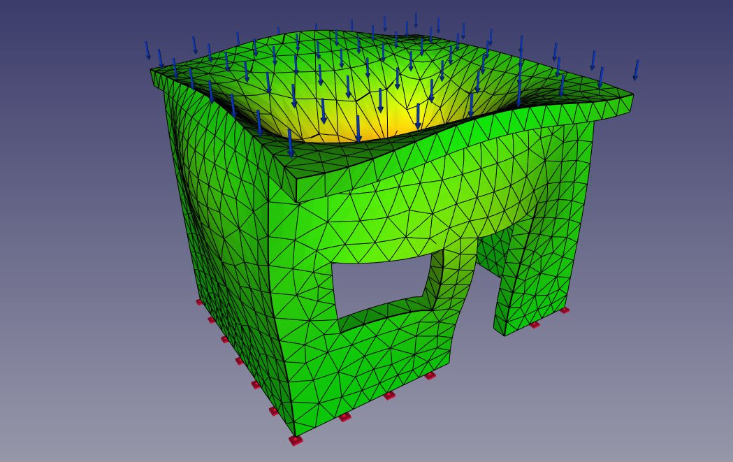
- Set the type of result that you want to see on the mesh, for example "absolute displacement", tick the show checkbox under Displacement, and move the slider next to it. You will be able to see the deformation growing as you apply more force:
The results displayed by the FEM workbench are of course currently not enough to perform real-life decisions about structures dimensioning and materials. However, they can already give precious information about how the forces flow through a structure, and which are the weak areas that will bear the more stress.
Downloads
- The file created during this exercise: https://github.com/yorikvanhavre/FreeCAD-manual/blob/master/files/fem.FCStd
Read more
