Manual:BIM modeling/it: Difference between revisions
Renatorivo (talk | contribs) (Created page with "Si noti che abbiamo disegnato sempre nella stessa direzione (in senso orario). Questo non è necessario, ma farà in modo che le pareti che noi costruiremo in seguito abbiano...") |
Renatorivo (talk | contribs) |
||
| Line 31: | Line 31: | ||
Si noti che abbiamo disegnato sempre nella stessa direzione (in senso orario). Questo non è necessario, ma farà in modo che le pareti che noi costruiremo in seguito abbiano tutte la stessa direzione, sinistra e destra. Si potrebbe anche pensare che qui avremmo potuto semplicemente disegnare un rettangolo, il che è vero. Ma le quattro linee ci permetteranno di illustrare meglio come aggiungere un oggetto in un altro. |
Si noti che abbiamo disegnato sempre nella stessa direzione (in senso orario). Questo non è necessario, ma farà in modo che le pareti che noi costruiremo in seguito abbiano tutte la stessa direzione, sinistra e destra. Si potrebbe anche pensare che qui avremmo potuto semplicemente disegnare un rettangolo, il che è vero. Ma le quattro linee ci permetteranno di illustrare meglio come aggiungere un oggetto in un altro. |
||
* |
* Selezionare la prima linea, quindi premere il pulsante [[Image:Arch_Wall.png|16px]] [[Arch Wall/it|Muro]]. |
||
* Ripetere questa operazione per le altre 3 linee, fino a quando si dispone di 4 muri. |
|||
* Repeat this for the 3 other lines, untilyou have 4 walls. |
|||
* |
* Selezionare le quattro mura, e impostare la loro proprietà '''Height''' a '''3.00 m''' e la loro proprietà '''Alignment''' su '''left'''. Se non si tracciano le linee nello stesso ordine come abbiamo fatto in precedenza, alcune delle pareti potrebbero avere le loro direzioni sinistra e destra capovolte, e Alignement potrebbe dover essere invece impostato su '''right''' . Si otterranno quattro pareti intersecanti, all'interno delle linee di base: |
||
[[Image:Exercise_arch_04.jpg]] |
[[Image:Exercise_arch_04.jpg]] |
||
Revision as of 21:06, 19 September 2016
- Introduzione
- Scoprire FreeCAD
- Lavorare con FreeCAD
- Script Python
- La Comunità
BIM sta per Building Information Modeling (Modello d'Informazioni di un Edificio). La definizione esatta di ciò che è varia, ma possiamo dire semplicemente che è il modo attuale di modellare gli edifici e le altre strutture di grandi dimensioni, come ponti, gallerie, ecc ... I modelli BIM sono di solito basate su modelli 3D, e comprendono anche una serie di ulteriori strati di informazioni, come le informazioni sui materiali, le relazioni con altri oggetti o modelli, o le istruzioni speciali per la costruzione o la manutenzione. Queste informazioni supplementari consentono tutti i tipi di analisi avanzate del modello, come ad esempio la resistenza strutturale, i costi e le stime dei tempi di costruzione, o il calcolo del consumo energetico.
L'ambiente Arch di FreeCAD implementa una serie di strumenti e servizi per la modellazione BIM. Anche se ha uno scopo diverso, è fatto per lavorare in stretta integrazione con il resto di FreeCAD. Qualsiasi cosa fatta con qualsiasi altro ambiente di FreeCAD può diventare un oggetto Arch, o essere utilizzato come base per un oggetto Arch.
Come nell'ambiente PartDesign, gli oggetti prodotti dall'ambiente Arch sono destinati ad essere costruiti nel mondo reale. Pertanto, devono essere solidi. Gli strumenti ad Arch di solito si prendono cura di questo automaticamente, e forniscono anche degli strumenti di utilità per facilitare la verifica della validità degli oggetti.
L'ambiente Arch comprende anche tutti gli strumenti di Draft, e usa la sua griglia e il sistema di aggancio. Prima di iniziare, è sempre una buona idea sfogliare le pagine delle preferenze di entrambi, Draft e Arch, e definire le impostazioni di default secondo i vostri gusti.
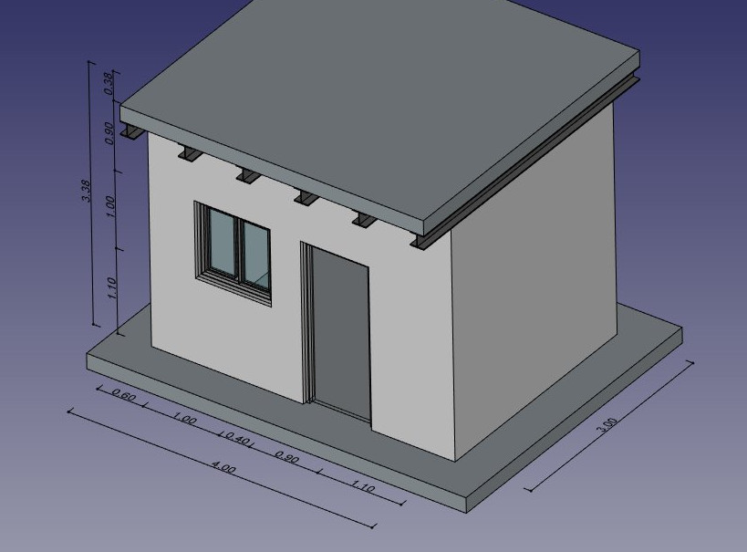
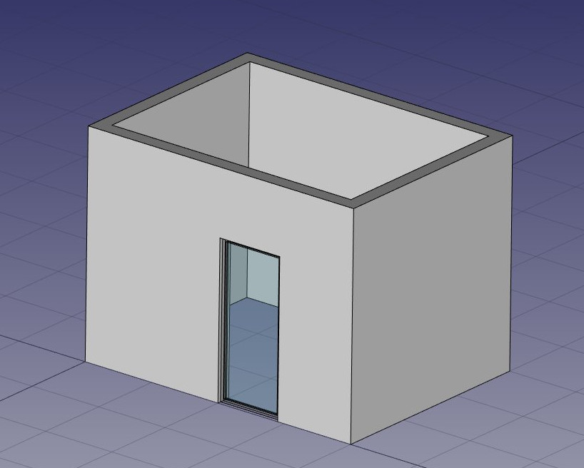
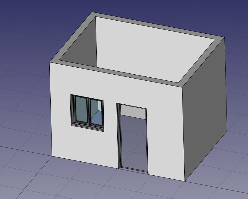
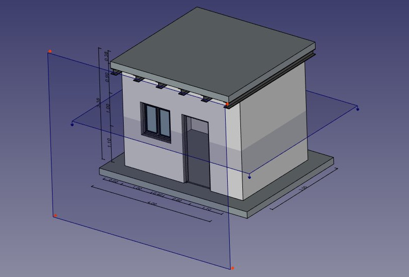
In questo capitolo, vedremo come modellare questo piccolo edificio:
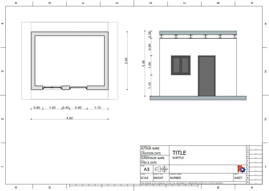
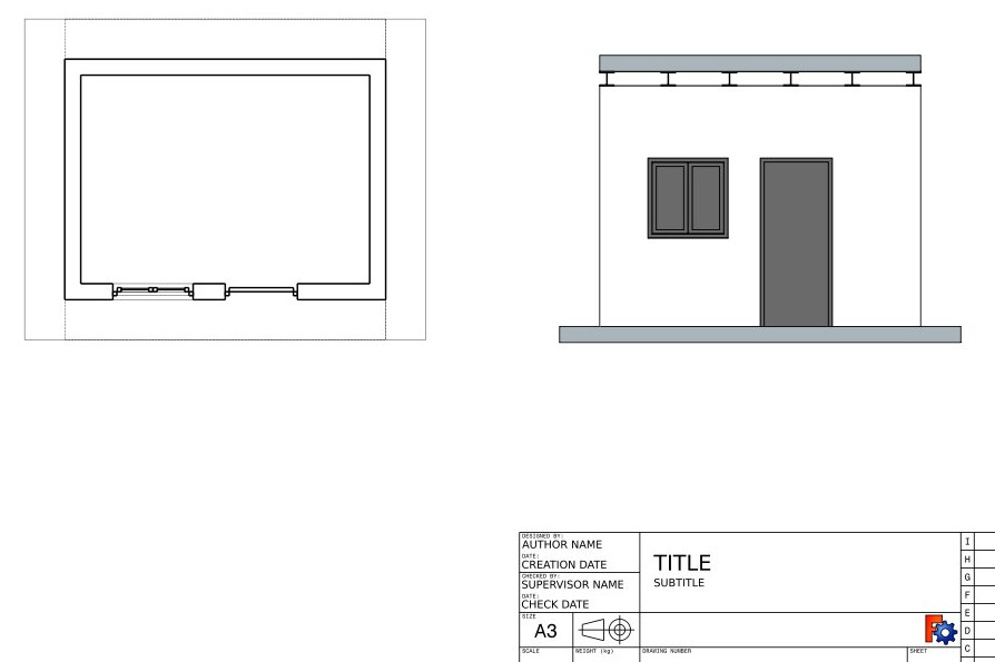
e produrre un piano e una vista in sezione da esso:
- Creare un nuovo documento e passare all'ambiente Arch.
- Aprire il menu Modifica -> Preferenze -> Draft -> Griglia e Snap e impostare la spaziatura della griglia a 1000 mm, in questo modo abbiamo una griglia da un metro, che sarà adatta alla dimensione del nostro edificio.
- Nella barra degli strumenti snap, assicurarsi che il pulsante File:Snap Grid.png Aggancia alla griglia sia attivato, in modo da poter utilizzare la griglia per quanto possibile.
- Impostare come Piano di lavoro il piano XY
- Disegnare quattro linee con lo strumento
 Linea. È possibile inserire le coordinate manualmente, o semplicemente scegliere i punti sulla griglia con il mouse:
- Dal punto (0,0) al punto (0,3)
- Dal punto (0,3) al punto (4,3)
- Dal punto (4,3) al punto (4,0)
- Dal punto (4,0) al punto (0,0)
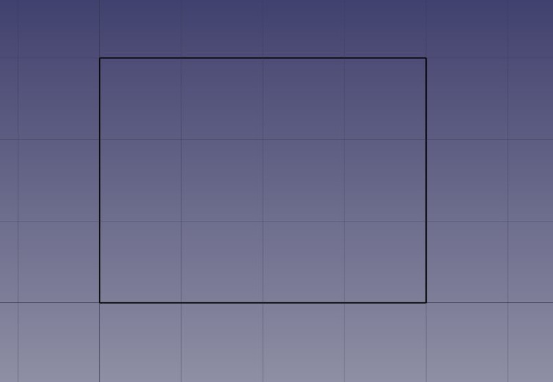
Si noti che abbiamo disegnato sempre nella stessa direzione (in senso orario). Questo non è necessario, ma farà in modo che le pareti che noi costruiremo in seguito abbiano tutte la stessa direzione, sinistra e destra. Si potrebbe anche pensare che qui avremmo potuto semplicemente disegnare un rettangolo, il che è vero. Ma le quattro linee ci permetteranno di illustrare meglio come aggiungere un oggetto in un altro.
- Selezionare la prima linea, quindi premere il pulsante
 Muro.
Muro. - Ripetere questa operazione per le altre 3 linee, fino a quando si dispone di 4 muri.
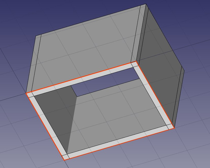
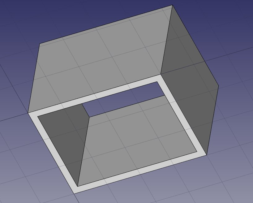
- Selezionare le quattro mura, e impostare la loro proprietà Height a 3.00 m e la loro proprietà Alignment su left. Se non si tracciano le linee nello stesso ordine come abbiamo fatto in precedenza, alcune delle pareti potrebbero avere le loro direzioni sinistra e destra capovolte, e Alignement potrebbe dover essere invece impostato su right . Si otterranno quattro pareti intersecanti, all'interno delle linee di base:
Now we need to join these walls together, so they intersect properly. This is not necessary when your walls are drawn in a way that they already connect cleanly, but here we need to, since they are intersecting. In Arch, this is done by electing one of the walls to be the "host", and adding the others to it, as "additions". All arch objects can have any number of additions (objects whose geometry will be added to the host's geometry), and subtractions (objects whose geometry will be subtracted). The additions and subtractions of an object can be managed anytime by double-clicking the object in the tree.
- Select the four walls with Ctrl pressed, the last one being the wall that you chose to become the host
- Press the
 Add button. The four walls have now been turned into one:
The individual walls are however still accessible, by expanding the wall in the tree view.
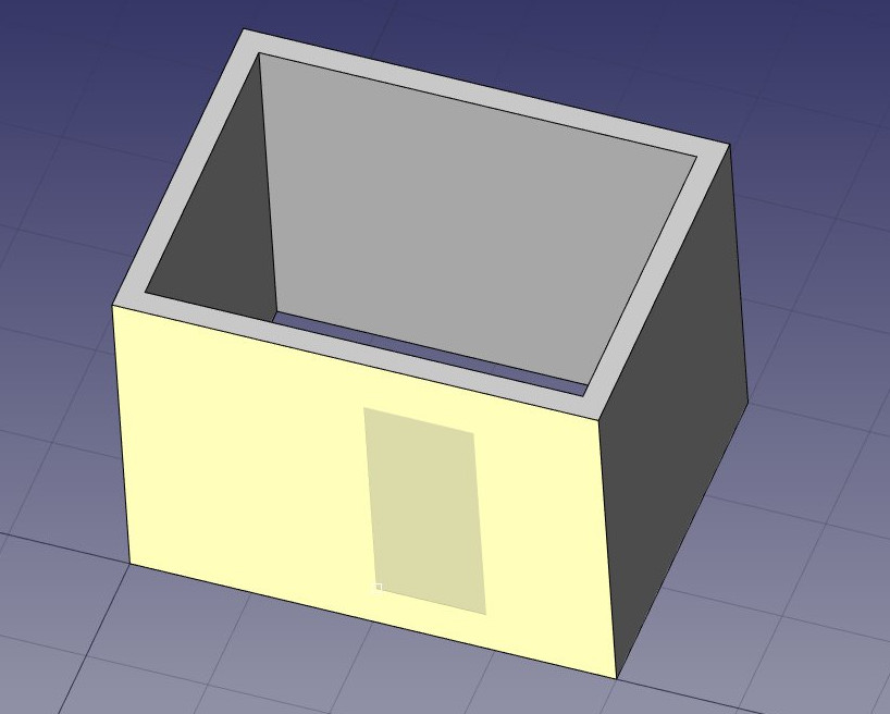
- Let's now place a door. In FreeCAD, doors are considered a special case of windows, so this is done using the Window tool.
- Start by selecting the wall. This is not necessary, but a good habit to take. If an object is selected when starting the window tool, you will force the window to be inserted in that object, even if you snap to another object.
- Set the Working Plane to auto so we are not restricted to the ground plane
- Press the
 Window button.
 - In the window creation panel, select the Simple door preset, and set its Width to 0.9m and its Height to 2.1m
- Make sure the File:Snap Near.png Near snap location is turned on, so we can snap on faces
- Place your window roughly on the middle of the front face of the wall:
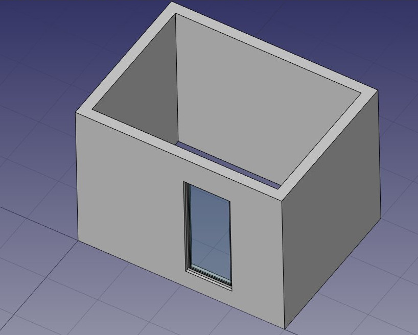
- After clicking, our window is placed on the correct face, but not exactly where we want:
- We can now set the precise location by expanding the wall and the window objects in the tree view, and changing the Placement property of the base sketch of our door. Set its position to x = 2m, y = 0, z = 0. Our window is now exactly where we want it:
- Repeat the operation to place a window: Select the wall, press the window tool, select the Open 2-pane preset, and place a 1m x 1m window in the same face as the door. Set the placement of the underlying sketch to position x = 0.6m, y = 0, z = 1.1m, so the upper line of the window is aligned to the top of the door.
Windows are always built on sketches. It is easy to create custom windows by first creating a sketch on a face, then turning it into a window by selecting it, then pressing the window button. Then, the window creation parameters, that is, which wires of the sketch must be extruded and how much, can be defined by double-clickingthe window in the tree view. Let's now create a slab:
- Set the Working Plane to XY plane
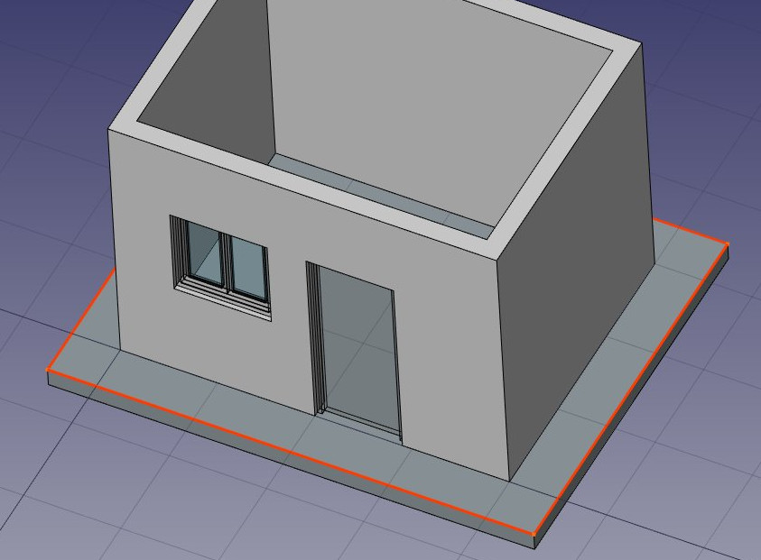
- Create a
 rectangle with a length of 5m, a height of 4m, and place it at position x:-0.5m, y:-0.5m, z:0.
 - Select the rectangle
- Click the
 structure tool to create a slab from the rectangle
 - Set the height property of the slab to 0.2m and its normal direction to (0,0,-1) because we want it to extrude downwards. We could also simply have moved it 0.2m down, but it is always good practice to keep extruded objects at the same place as their base profile.
- Set the Role property of the slab to slab. This is not necessary in FreeCAD, but is important for IFC export, as it will ensure that the object is exported with the correct IFC type.
- Let's now use one of the structural presets to make a metallic beam. Click the
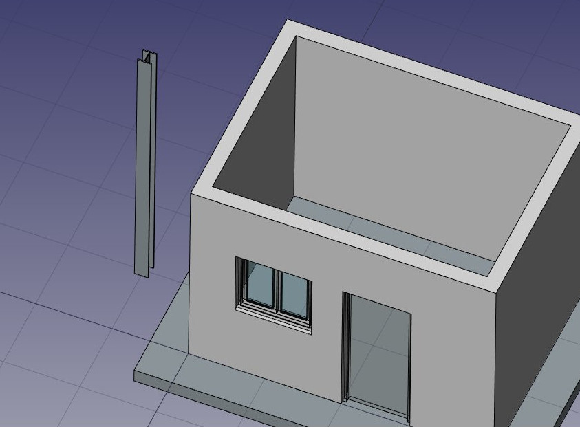
 structure button, select a HEB 180 preset, and set its height to 4m. Place it anywhere:
- Adjust its placement by setting its rotation to 90° in the (1,0,0) axis, and its position to x:90mm, y:3.5m, z:3.09m. This will position the beam exactly on one of the side walls:
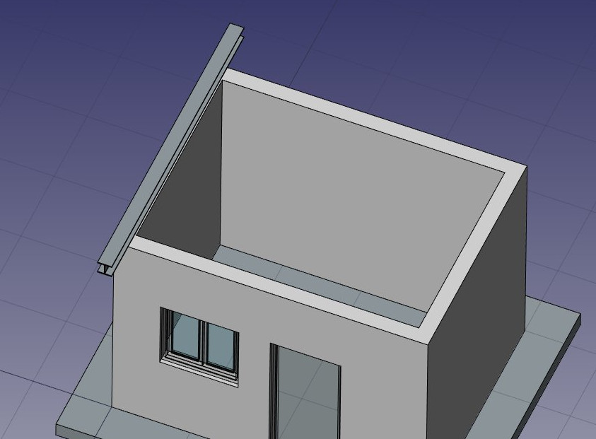
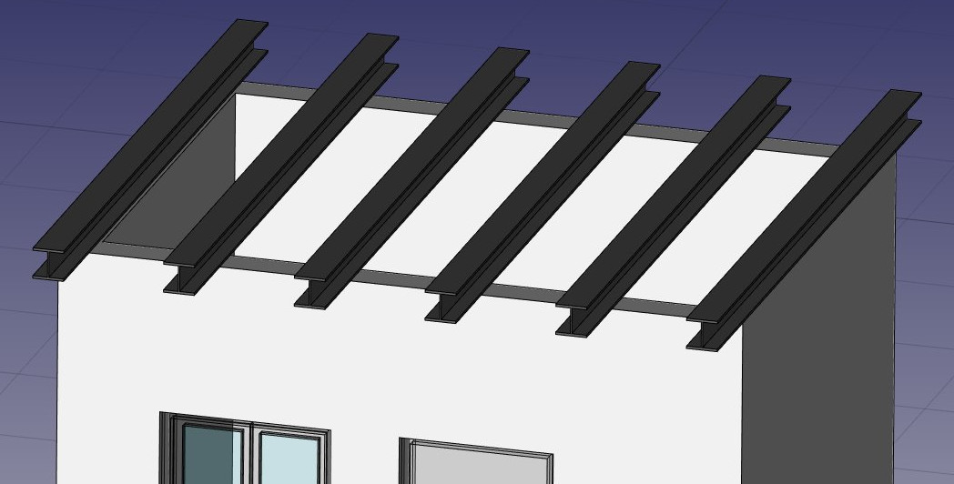
- We need now to duplicate this beam a couple of times. We could do that one by one using the
 clone tool, but there is a better way, to do all the copies at once using an array:
 - Select the beam
- Press the
 Array button
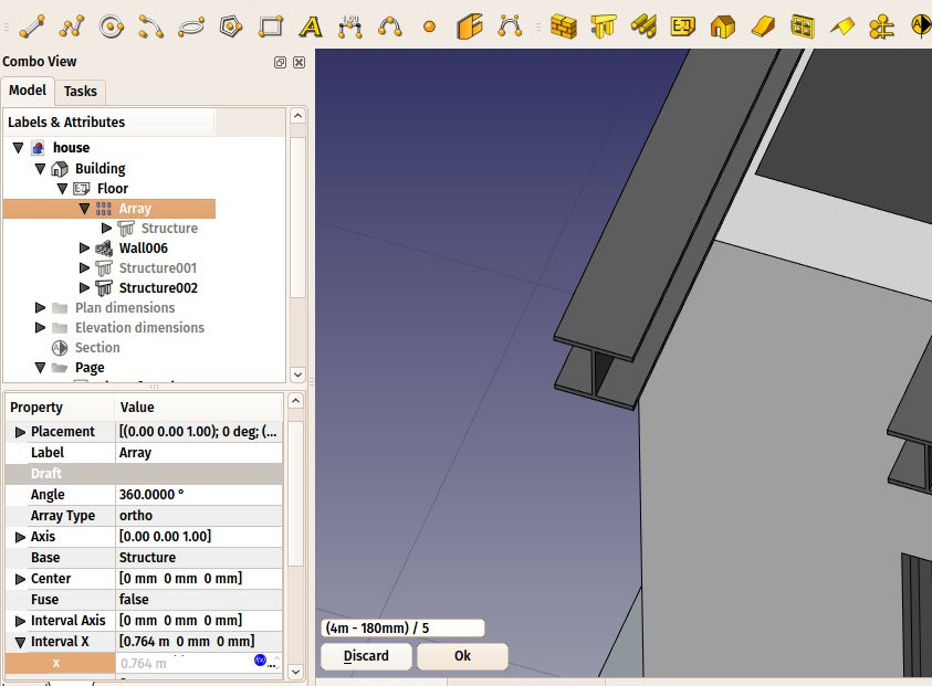
 - Set the Number X property of the array to 6, leave the Y and Z numbers to 1
- Expand the interval X property, and press the small
 expression icon at the right side of the X field. This will open an expressions editor:
- Write (4m-180mm)/5 in the expression field, and press OK. This will set the x value to 0.764 (4m is the total length of our front wall, 180mm is the width of the beam, which is why it is called HEB180, and we want a fifth of that space as interval between each beam):
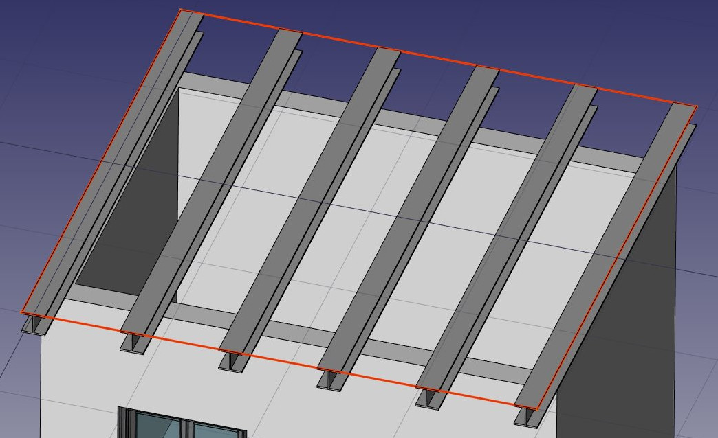
- We can now easily build a simple slab on top of them, by drawing a rectangle directly on the top plane of the beams. Select a top face of one of the beams
- Press the
 working plane button. The working plane is now set to that face.
 - Create a
 rectangle, snapping to two opposite points of the border beams:
- Select the rectangle
- Click the
 structure button and create a slab with a height of 0.2m.
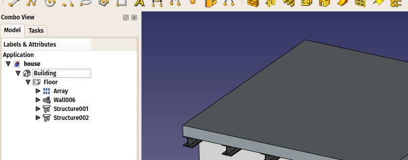
That's it, our model is now complete. We should now organize it so it exports correctly to IFC. The IFC format requires that all objects of a building are inside a building object, and optionally, inside a storey. It also requires that all buildings are placed on a site, but the IFC exporter of FreeCAD will add a default site automatically if needed, so we don't need to add one here.
- Select the two slabs, the wall, and the array of beams
- Press the
 Floor button
 - Select the floor we just created
- Press the
 Building button
Our model is now ready to export:
The IFC format is one of the most precious assets in a free BIM world, because it allows the exchange of data between any application and actor of the construction world, in an open manner (the format is open, free and maintained by an independent consortium). Exporting your BIM models as IFC ensures that anyone can see and analyze them, no matter the application used.
In FreeCAD, IFC import and export is done by interfacing with another piece of software, called IfcOpenShell. To be able to export to IFC from FreeCAD, the IfcOpenShell-python package must be installed on your system. Be sure to select one which uses the same python version as FreeCAD. The python version that FreeCAD uses is informed when opening the View -> Panels -> Python console panel in FreeCAD. When that is done, we can now export our model:
- Select the top object you want to export, that is, the Building object.
- Select menu File -> Export -> Industry Foundation Classes and save your file.
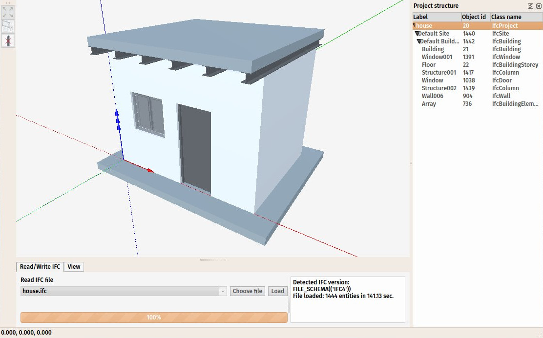
- The resulting IFC file can now be opened ina wide range of applications and viewers (the image below shows the file opened in the free IfcPlusPlus viewer). Checking the exported file in such a viewer application before distributing it to other people is important to check that all the data contained in the file is correct. FreeCAD itself can also be used to re-open the resulting IFC file.
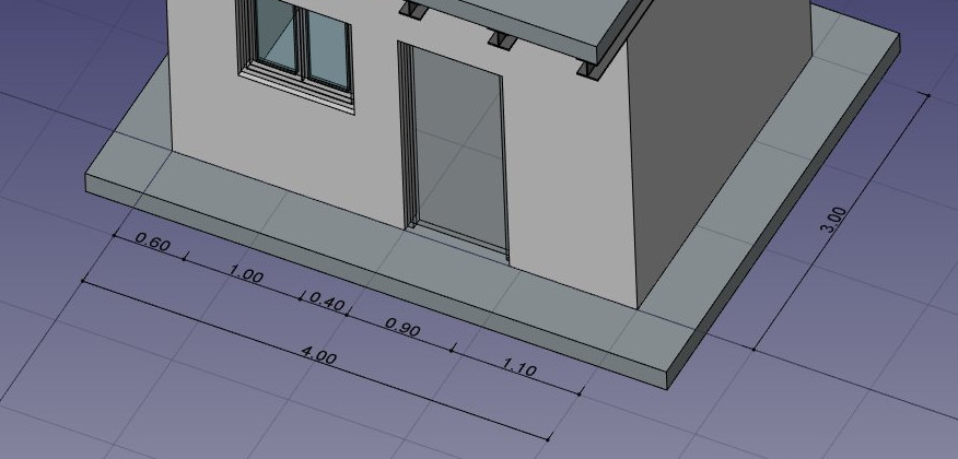
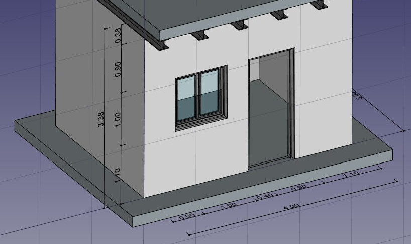
We will now place some dimensions. Unlike the previous chapter, where we drew all the dimensions directly on the Drawing sheet, we will use another method here, and place Draft dimensions directly in the 3D model. These dimensions will then be placed on the Drawing sheet. We will first make two groups for our dimensions, one for the dimensions that will appear in the plan view, and another for those that appear on the elevation.
- Right-click the "house" document in the tree view, and create two new groups: Plan dimensions and Elevation dimensions.
- Set the Working Plane to XY plane
- Make sure the File:Snap WorkingPlane.png restrict snap location is turned on, so everything you draw stays on the working plane.
- Draw a couple of
 dimensions, for example as on the image below. Pressing Shift and Ctrl while snapping the dimension points will give you additional options.
- Select all your dimensions, and drag them to the Plan dimensions group in the tree view
- Set the Working Plane to XZ plane, that is, the frontal vertical plane.
- Repeat the operation, draw a couple of dimensions, and place them in the Elevation dimensions group.
We will now prepare a set of views from our model, to be paced on a Drawing page. We can do that with the tools from the Drawing Workbench, as we have seen in the previous chapter, but the Arch Workbench also offers an all-in-one advanced tool to produce plan, section and elevation views, called Section Plane. We will now add two of these section planes, to create a plan view and an elevation view.
- Select the building object in the tree view
- Press the
 Section Plane button.
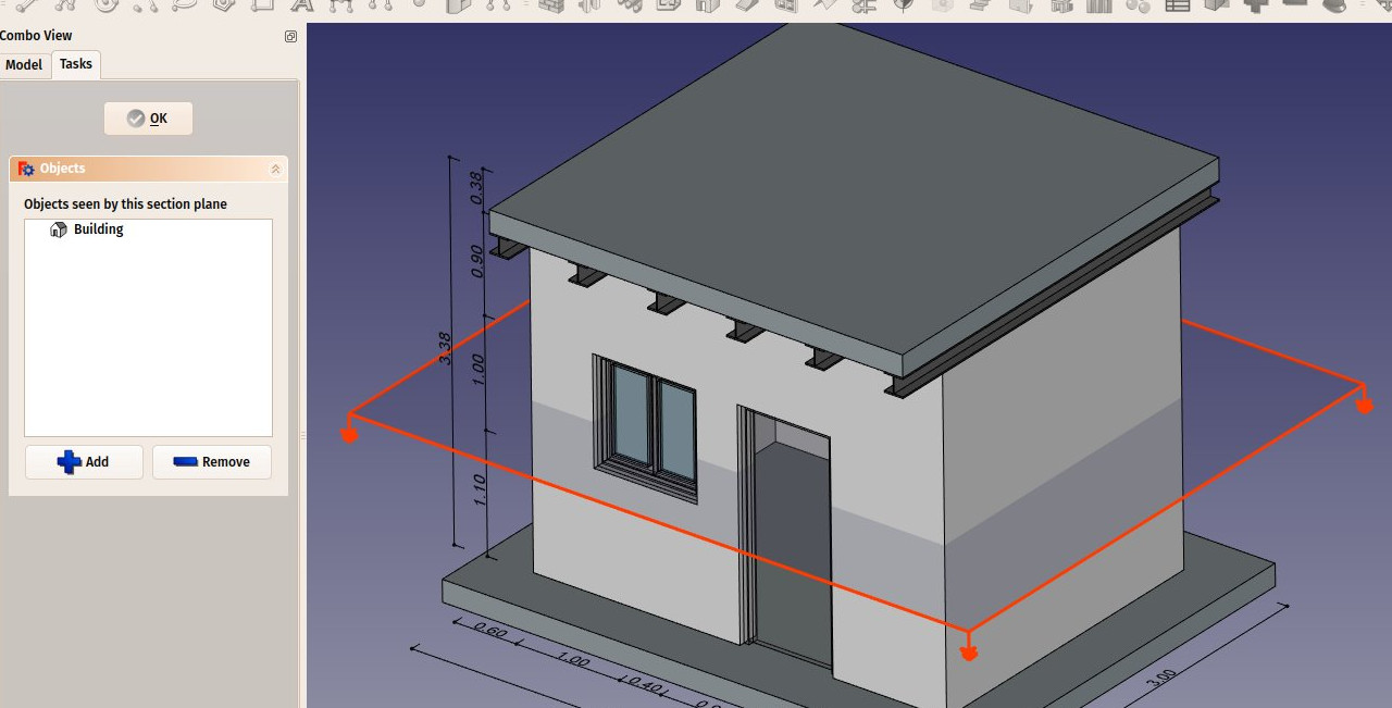
 - Set its Display Height property to 5m, its Display Length to 6m, so we encompass our house (this is not needed, but will look better, as it will show naturally what it is used for), and its Placement position at x:2m, y:1.5m, z:1.5m.
- Check the list of objects considered by the Section Plane by double-clicking it in the tree view. Section Planes only render specified objects from the model, not all of them. The objects considered by the Section Plane can be changed here.
- Repeat the operation to create another section plane, give it the same display length and height, and give it the following Placement: position: x:2m, y:-2m, z:1.5m, angle: 90°, axis: x:1, y:0, z:0. Make sure this new section plane also considers the building object.
- Now we have everything we need, and we can create our Drawing page. Start by switching to the Drawing Workbench, and create a new default
 A3 page (or select another template if you wish).
 - Select the first section plane, used for the plan view
- Press the
 Draft View button. This tool offers a couple of additional features over the standard Drawing View tool, and supports the Section Planes from the Arch Workbench.
 - Give the new view the following properties:
- X: 50
- Y: 140
- Scale: 0.03
- Line width: 0.15
- Show Cut True
- Show Fill: True
- Select the other section plane, and create a new Draft View, with the followng properties:
- X: 250
- Y: 150
- Scale: 0.03
- Rendering: Solid
We will now create two more Draft Views, one for each group of dimensions.
- Select the Plan dimensions group
- Press the
 Draft View button.
 - Give the new view the following properties:
- X: 50
- Y: 140
- Scale: 0.03
- Line width: 0.15
- Font size: 10mm
- Repeat the operation for the other group, with the following settings:
- X: 250
- Y: 150
- Scale: 0.03
- Line width: 0.15
- Font size: 10mm
- Direction: 0,-1,0
- Rotation: 90°
Our page is now ready, and we can export it to SVG or DXF formats, or print it. The SVG format allows to open the file illustration applications such as inkscape, with which you can quickly enhance technical drawings and turn them into much nicer presentation drawings. It offers many more possibilities than the DXF format.
Downloads
- The file produced during this exercise: https://github.com/yorikvanhavre/FreeCAD-manual/blob/master/files/house.FCStd
- The IFC file exported from the above file: https://github.com/yorikvanhavre/FreeCAD-manual/blob/master/files/house.ifc
- The SVG file exported from the above file: https://github.com/yorikvanhavre/FreeCAD-manual/blob/master/files/house.svg
Read more
