Tutorial FreeCAD POV ray: Difference between revisions
(→Editing the .pov file: Small changes to the introduction) |
(Removed Tutorials_navi) |
||
| (22 intermediate revisions by 5 users not shown) | |||
| Line 2: | Line 2: | ||
<translate> |
<translate> |
||
<!--T:112--> |
|||
{{VeryImportantMessage|The [[Raytracing_Workbench|Raytracing workbench]] is being superseded by the new [https://github.com/FreeCAD/FreeCAD-render Render Workbench], which is intended as its replacement. The Render Workbench can be installed through the [[Std_AddonMgr|Addon Manager]]. The information here is provided because by default FreeCAD is still shipped (as of 0.19-24276) with the Raytracing Workbench, and because the new workbench should basically work in the same way}} |
|||
<!--T:1--> |
|||
{{TutorialInfo |
{{TutorialInfo |
||
|Topic=Rendering |
|Topic=Rendering |
||
|Level=Intermediate |
|Level=Intermediate |
||
|Time= |
|Time=120 minutes |
||
|Author=[https://forum.freecadweb.org/memberlist.php?mode=viewprofile&u=21943 vocx] |
|Author=[https://forum.freecadweb.org/memberlist.php?mode=viewprofile&u=21943 vocx] |
||
|FCVersion=0.18 or greater |
|FCVersion=0.18 or greater |
||
| Line 11: | Line 15: | ||
}} |
}} |
||
==Introduction== |
==Introduction== <!--T:2--> |
||
<!--T:3--> |
|||
This tutorial shows how to produce a rendered image in FreeCAD, using the POV-Ray renderer. It assumes that the user already created a part or assembly in FreeCAD, or has imported one into it. It uses the [[Raytracing Workbench]] to produce the file for rendering. |
This tutorial shows how to produce a rendered image in FreeCAD, using the POV-Ray renderer. It assumes that the user already created a part or assembly in FreeCAD, or has imported one into it. It uses the [[Raytracing Workbench]] to produce the file for rendering. |
||
<!--T:4--> |
|||
This tutorial is based on the forum post by schupin [https://forum.freecadweb.org/viewtopic.php?f=36&t=32745 FreeCAD / pov ray tutorial], which also includes one {{incode|.pov}} file required to produce a rendering. |
This tutorial is based on the forum post by schupin [https://forum.freecadweb.org/viewtopic.php?f=36&t=32745 FreeCAD / pov ray tutorial], which also includes one {{incode|.pov}} file required to produce a rendering. |
||
| Line 21: | Line 27: | ||
<translate> |
<translate> |
||
<!--T:5--> |
|||
{{Caption|align=center|Example by schupin of a 3D model and high quality render produced with FreeCAD and POV-Ray.}} |
{{Caption|align=center|Example by schupin of a 3D model and high quality render produced with FreeCAD and POV-Ray.}} |
||
<!--T:6--> |
|||
The files used in this tutorial are in another post in the same thread [https://forum.freecadweb.org/viewtopic.php?f=36&t=32745 FreeCAD / pov ray tutorial (pending)]. |
|||
The files used in this tutorial are in post #8 [https://forum.freecadweb.org/viewtopic.php?f=36&t=32745#p305169 in the same thread]. |
|||
==Basic setup== |
==Basic setup== <!--T:7--> |
||
<!--T:8--> |
|||
Follow the basic workflow outlined in the [[Raytracing Workbench]] documentation. |
Follow the basic workflow outlined in the [[Raytracing Workbench]] documentation. |
||
<!--T:9--> |
|||
For direct rendering to work, the {{incode|povray}} executable must be set in {{MenuCommand|Edit → Preferences → Raytracing → Render → POV-Ray executable}}; set it to its location in your system, for example, {{incode|/usr/bin/povray}}. Other options used by the renderer can be defined here as well, including the width {{incode|+W}} and height {{incode|+H}} of the image, and the use of antialiasing {{incode|+A}}. |
For direct rendering to work, the {{incode|povray}} executable must be set in {{MenuCommand|Edit → Preferences → Raytracing → Render → POV-Ray executable}}; set it to its location in your system, for example, {{incode|/usr/bin/povray}}. Other options used by the renderer can be defined here as well, including the width {{incode|+W}} and height {{incode|+H}} of the image, and the use of antialiasing {{incode|+A}}. |
||
==Setup the .pov file== |
==Setup the .pov file== <!--T:10--> |
||
<!--T:11--> |
|||
1. Create an assembly using bodies from the [[Part Workbench|Part]] or [[PartDesign Workbench|PartDesign Workbenches]], or any other workbench that produces solid objects, for example, the [[Arch Workbench]]. Assign colors or materials to the individual bodies that make the assembly, approximately matching the color that you want in your render. |
|||
1. Create an assembly using bodies from the [[Part_Workbench|Part]] or [[PartDesign_Workbench|PartDesign Workbenches]], or any other workbench that produces solid objects, for example, the [[Arch Workbench]]. Assign colors or materials to the individual bodies that make the assembly, approximately matching the color that you want in your render. |
|||
</translate> |
</translate> |
||
| Line 39: | Line 50: | ||
<translate> |
<translate> |
||
<!--T:12--> |
|||
{{Caption|align=center|Assembly of three bodies created in FreeCAD, and with colors or materials assigned.}} |
{{Caption|align=center|Assembly of three bodies created in FreeCAD, and with colors or materials assigned.}} |
||
<!--T:13--> |
|||
2. If your model is very detailed, make sure the {{PropertyView|Deviation}} of the body is set to a low value, between {{incode|0.1}} and {{incode|0.01}}, or even smaller. The lower this value is, the more detailed the exported mesh will be, and thus the better the quality of the render will be. |
2. If your model is very detailed, make sure the {{PropertyView|Deviation}} of the body is set to a low value, between {{incode|0.1}} and {{incode|0.01}}, or even smaller. The lower this value is, the more detailed the exported mesh will be, and thus the better the quality of the render will be. |
||
<!--T:14--> |
|||
[[Image:02_T04_FreeCAD_POVray_deviation.png|center]] |
[[Image:02_T04_FreeCAD_POVray_deviation.png|center]] |
||
<!--T:15--> |
|||
{{Caption|align=center|Deviation property of the bodies created in FreeCAD; the deviation needs to be small in order to export the parts with good resolution.}} |
{{Caption|align=center|Deviation property of the bodies created in FreeCAD; the deviation needs to be small in order to export the parts with good resolution.}} |
||
<!--T:16--> |
|||
3. Create a POV-Ray project by clicking {{Button|[[Image:Raytrace_New.svg|16px]] [[Raytracing New|New]]}}. If the viewport is set as [[Std OrthographicCamera|orthographic]], change it to [[Std PerspectiveCamera|perspective]], as the renderer will normally work with a camera with perspective view. Using perspective view will allow you to see better the type of scene that will be rendered. |
3. Create a POV-Ray project by clicking {{Button|[[Image:Raytrace_New.svg|16px]] [[Raytracing New|New]]}}. If the viewport is set as [[Std OrthographicCamera|orthographic]], change it to [[Std PerspectiveCamera|perspective]], as the renderer will normally work with a camera with perspective view. Using perspective view will allow you to see better the type of scene that will be rendered. |
||
<!--T:17--> |
|||
4. Select all objects that you want to add to your scene, then select the created {{incode|PovProject}} object, and click on {{Button|[[Image:Raytrace_NewPartSegment.svg|16px]] [[Raytracing_InsertPart|InsertPart]]}}. |
4. Select all objects that you want to add to your scene, then select the created {{incode|PovProject}} object, and click on {{Button|[[Image:Raytrace_NewPartSegment.svg|16px]] [[Raytracing_InsertPart|InsertPart]]}}. |
||
<!--T:18--> |
|||
{{Emphasis|Note:}} beware of those objects that are not currently visible in the 3D viewport. If they are invisible but are included in the scene, they will still be rendered. On the other hand, if you really want to omit a body from being rendered, don't select it for inclusion into the POV-Ray project. |
{{Emphasis|Note:}} beware of those objects that are not currently visible in the 3D viewport. If they are invisible but are included in the scene, they will still be rendered. On the other hand, if you really want to omit a body from being rendered, don't select it for inclusion into the POV-Ray project. |
||
<!--T:19--> |
|||
{{Emphasis|Note 2:}} all objects in the POV-Ray project will have a name based on their internal FreeCAD name. It's important to note which is the POV-Ray name, as further options, for example, the material textures, will be assigned to these POV-Ray names. |
{{Emphasis|Note 2:}} all objects in the POV-Ray project will have a name based on their internal FreeCAD name. It's important to note which is the POV-Ray name, as further options, for example, the material textures, will be assigned to these POV-Ray names. |
||
<!--T:20--> |
|||
5. In the 3D viewport, zoom, pan and rotate the view to setup the scene as you want. Make sure the objects are centered in the viewport, then select the created {{incode|PovProject}} object, and press {{Button|[[Image:Raytrace_ResetCamera.svg|16px]] [[Raytracing ResetCamera|ResetCamera]]}}. |
5. In the 3D viewport, zoom, pan and rotate the view to setup the scene as you want. Make sure the objects are centered in the viewport, then select the created {{incode|PovProject}} object, and press {{Button|[[Image:Raytrace_ResetCamera.svg|16px]] [[Raytracing ResetCamera|ResetCamera]]}}. |
||
<!--T:21--> |
|||
6. The POV-Ray file is now ready; it contains the selected objects and the camera information. Select the created {{incode|PovProject}} object, and then press {{Button|[[Image:Raytrace_ExportProject.svg|16px]] [[Raytracing ExportProject|ExportProject]]}} to save the {{incode|.pov}} file. |
6. The POV-Ray file is now ready; it contains the selected objects and the camera information. Select the created {{incode|PovProject}} object, and then press {{Button|[[Image:Raytrace_ExportProject.svg|16px]] [[Raytracing ExportProject|ExportProject]]}} to save the {{incode|.pov}} file. |
||
<!--T:22--> |
|||
7. The created {{incode|.pov}} file can now be rendered directly from FreeCAD. Select the created {{incode|PovProject}} object, then press {{Button|[[Image:Raytrace_Render.svg|16px]] [[Raytracing_Render|Render]]}}. When the popup image appears on screen, click on it so that it is sent to FreeCAD in its own window tab. |
7. The created {{incode|.pov}} file can now be rendered directly from FreeCAD. Select the created {{incode|PovProject}} object, then press {{Button|[[Image:Raytrace_Render.svg|16px]] [[Raytracing_Render|Render]]}}. When the popup image appears on screen, click on it so that it is sent to FreeCAD in its own window tab. |
||
| Line 65: | Line 87: | ||
<translate> |
<translate> |
||
<!--T:23--> |
|||
{{Caption|align=center|First render of the assembly produced with POV-Ray, with the standard template written by the Raytracing Workbench.}} |
{{Caption|align=center|First render of the assembly produced with POV-Ray, with the standard template written by the Raytracing Workbench.}} |
||
<!--T:24--> |
|||
7.1. With the {{incode|.pov}} file already created, it is also possible to run {{incode|povray}} from the command line. |
7.1. With the {{incode|.pov}} file already created, it is also possible to run {{incode|povray}} from the command line. |
||
</translate> |
</translate> |
||
| Line 74: | Line 98: | ||
<translate> |
<translate> |
||
<!--T:25--> |
|||
The options {{incode|+WX +HY}} set the horizontal and vertical pixel sizes of the final image. |
The options {{incode|+WX +HY}} set the horizontal and vertical pixel sizes of the final image. |
||
<!--T:26--> |
|||
The options {{incode|+AM2}} (type 2, recursive super-sampling) and {{incode|+A}} trigger antialiasing to produce a smoother image. |
The options {{incode|+AM2}} (type 2, recursive super-sampling) and {{incode|+A}} trigger antialiasing to produce a smoother image. |
||
<!--T:27--> |
|||
8. By double clicking the {{incode|PovProject}} object it's possible to see that it is using the {{incode|ProjectStd.pov}} template; this template creates a basic {{incode|.pov}} file which will produce a simple and dark image. |
8. By double clicking the {{incode|PovProject}} object it's possible to see that it is using the {{incode|ProjectStd.pov}} template; this template creates a basic {{incode|.pov}} file which will produce a simple and dark image. |
||
<!--T:28--> |
|||
To improve the appearance of the image, use a better template. Double click the {{incode|PovProject}} object and choose the {{incode|RadiosityNormal.pov}} template. Then export a new {{incode|.pov}} file, and run again the renderer. The image should look brighter and generally better. |
To improve the appearance of the image, use a better template. Double click the {{incode|PovProject}} object and choose the {{incode|RadiosityNormal.pov}} template. Then export a new {{incode|.pov}} file, and run again the renderer. The image should look brighter and generally better. |
||
| Line 86: | Line 114: | ||
<translate> |
<translate> |
||
<!--T:29--> |
|||
{{Caption|align=center|Render of the assembly produced with POV-Ray, with the RadiosityNormal template written by the Raytracing Workbench.}} |
{{Caption|align=center|Render of the assembly produced with POV-Ray, with the RadiosityNormal template written by the Raytracing Workbench.}} |
||
<!--T:30--> |
|||
Once again double click the {{incode|PovProject}} object and now choose the {{incode|RadiosityOutdoorHQ.pov}} template. Then export a new {{incode|.pov}} file, and run again the renderer. The image should take longer to produce, but the result should have better quality. |
Once again double click the {{incode|PovProject}} object and now choose the {{incode|RadiosityOutdoorHQ.pov}} template. Then export a new {{incode|.pov}} file, and run again the renderer. The image should take longer to produce, but the result should have better quality. |
||
</translate> |
</translate> |
||
| Line 93: | Line 123: | ||
<translate> |
<translate> |
||
<!--T:31--> |
|||
{{Caption|align=center|Render of the assembly produced with POV-Ray, with the RadiosityOutdoorHQ template written by the Raytracing Workbench.}} |
{{Caption|align=center|Render of the assembly produced with POV-Ray, with the RadiosityOutdoorHQ template written by the Raytracing Workbench.}} |
||
<!--T:32--> |
|||
If the rendered image is good enough, then it can be saved, and there is nothing more to do. However, in order to control precisely the appearance of the materials and produce even better results, the {{incode|.pov}} file needs to be edited manually. |
If the rendered image is good enough, then it can be saved, and there is nothing more to do. However, in order to control precisely the appearance of the materials and produce even better results, the {{incode|.pov}} file needs to be edited manually. |
||
<!--T:33--> |
|||
In the following sections, we edit the basic {{incode|.pov}} file produced with the {{incode|ProjectStd}} template. |
In the following sections, we edit the basic {{incode|.pov}} file produced with the {{incode|ProjectStd}} template. |
||
==Editing the .pov file== |
==Editing the .pov file== <!--T:34--> |
||
<!--T:35--> |
|||
9. The {{incode|.pov}} file generated by FreeCAD is a simple text file that can be opened with any editor. It loosely resembles a C++ source code file: directives start with a hash {{incode|#}} and are terminated by a semi-colon {{incode|;}}. Curly braces <code>{ }</code> are used to limit section blocks, and indentation is arbitrary white space. Comments are indicated with a double slash {{incode|//}}; block comments can be defined with a pair of {{incode|/* */}}, like in C. |
9. The {{incode|.pov}} file generated by FreeCAD is a simple text file that can be opened with any editor. It loosely resembles a C++ source code file: directives start with a hash {{incode|#}} and are terminated by a semi-colon {{incode|;}}. Curly braces <code>{ }</code> are used to limit section blocks, and indentation is arbitrary white space. Comments are indicated with a double slash {{incode|//}}; block comments can be defined with a pair of {{incode|/* */}}, like in C. |
||
<!--T:36--> |
|||
The file may look complicated at first but 90% of its content is just mesh data that doesn't require many changes, as these meshes represent the geometry of the bodies that we want to render. |
The file may look complicated at first but 90% of its content is just mesh data that doesn't require many changes, as these meshes represent the geometry of the bodies that we want to render. |
||
<!--T:37--> |
|||
The file is structured as follows: |
The file is structured as follows: |
||
* Includes |
* Includes |
||
| Line 115: | Line 151: | ||
* Light source |
* Light source |
||
<!--T:38--> |
|||
The camera information will not be touched, neither most information in the meshes. The main modifications will be made on the other sections. |
The camera information will not be touched, neither most information in the meshes. The main modifications will be made on the other sections. |
||
<!--T:39--> |
|||
As the meshes won't be heavily modified, the file can be re-organized so this information is at the end of the file. |
As the meshes won't be heavily modified, the file can be re-organized so this information is at the end of the file. |
||
<!--T:40--> |
|||
=== Basic re-organization === |
|||
<div class="toccolours mw-collapsible mw-collapsed"> |
|||
This is the complete content of the {{incode|.pov}} file, only without the meshes. |
|||
<div class="mw-collapsible-content"> |
|||
</translate> |
|||
{{Code|code= |
|||
// Persistence of Vision Ray Tracer Scene Description File |
|||
// for FreeCAD (http://www.freecadweb.org) |
|||
#version 3.6; |
|||
#include "colors.inc" |
|||
#include "metals.inc" |
|||
// ---------------------------------------- |
|||
global_settings { |
|||
assumed_gamma 1.0 |
|||
ambient_light color rgb <1.0,1.0,1.0> |
|||
max_trace_level 20 |
|||
} |
|||
// ---------------------------------------- |
|||
sky_sphere { |
|||
pigment { |
|||
gradient y |
|||
color_map { |
|||
[0.0 rgb <0.6,0.7,1.0>] |
|||
[0.7 rgb <0.0,0.1,0.8>] |
|||
} |
|||
} |
|||
} |
|||
// ---------------------------------------- |
|||
plane { |
|||
y, -1 |
|||
texture { pigment {rgb <0.0,0.0,0.0>} finish {ambient 0.0 reflection 0.05 specular 0.0} } |
|||
} |
|||
// Standard finish |
|||
//#declare StdFinish = F_MetalA; |
|||
//#declare StdFinish = finish { diffuse 0.7 }; |
|||
//#declare StdFinish = finish { phong 0.5 }; |
|||
//#declare StdFinish = finish { ambient rgb <0.5,0.5,0.5> }; |
|||
//#declare StdFinish = finish { crand 0.5 phong 0.9}; |
|||
#declare StdFinish = finish { ambient 0.01 diffuse 0.9 phong 1.0 phong_size 70 metallic brilliance 1.5} ; |
|||
// declares position and view direction |
|||
// Generated by FreeCAD (http://www.freecadweb.org/) |
|||
#declare cam_location = <-171.753,1229.11,-2667.08>; |
|||
#declare cam_look_at = <636.959,359.955,160.296>; |
|||
#declare cam_sky = <0.068217,0.958943,0.275273>; |
|||
#declare cam_angle = 45; |
|||
camera { |
|||
location cam_location |
|||
look_at cam_look_at |
|||
sky cam_sky |
|||
angle cam_angle |
|||
right x*800/600 |
|||
} |
|||
// Written by FreeCAD http://www.freecadweb.org/ |
|||
// face number1 +++++++++++++++++++++++++++++++++++++++++++++++++++++++++++++++++++++ |
|||
// ... meshes should be defined here until the end of the file ... |
|||
//default light |
|||
light_source { |
|||
cam_location + cam_angle * 100 |
|||
color rgb <10, 10, 10> |
|||
} |
|||
}} |
|||
<translate> |
|||
<!--T:41--> |
|||
</div> |
|||
</div> |
|||
=== Basic re-organization === <!--T:42--> |
|||
<!--T:43--> |
|||
10. Open the {{incode|.pov}} file with a text editor, go to the end of the file, select and cut the {{incode|light_source}} section, and paste it before the first {{incode|//face number1}} line. |
10. Open the {{incode|.pov}} file with a text editor, go to the end of the file, select and cut the {{incode|light_source}} section, and paste it before the first {{incode|//face number1}} line. |
||
<!--T:44--> |
|||
The resulting file should have the {{incode|camera}} and {{incode|light_source}} sections next to each other, for example |
The resulting file should have the {{incode|camera}} and {{incode|light_source}} sections next to each other, for example |
||
| Line 153: | Line 276: | ||
<translate> |
<translate> |
||
=== Prepare lights === |
=== Prepare lights === <!--T:45--> |
||
<!--T:46--> |
|||
13. By default, the project file defines one light with a position and color. |
|||
11. By default, the project file defines one light with a position and color. |
|||
</translate> |
</translate> |
||
{{Code|code= |
{{Code|code= |
||
| Line 165: | Line 289: | ||
<translate> |
<translate> |
||
<!--T:47--> |
|||
The position of the light is defined by a vector. The {{incode|color}} of the light should be in the range {{incode|0.0}} to {{incode|1.0}} for it to have normal brightness; alternatively it could be a named color such as {{incode|White}}. |
|||
The position of the light is defined by a vector {{incode|<x, y, z>}}. The {{incode|color}} can be established like an {{incode|<r, g, b>}} vector or it could also be a named color such as {{incode|White}}. If the RGB values are given, they should be in the range {{incode|0.0}} to {{incode|1.0}} for the light to have normal brightness. |
|||
<!--T:48--> |
|||
Like other objects, the light can be modified with many options. The {{incode|area_light}} option creates a rectangular source, which is more realistic as it results in diffuse illumination that creates soft shadows. The {{incode|adaptive}} keyword helps reduce the computation time of the light paths; the larger the value the more accurate the result will be; to avoid long rendering times you should use the smallest integer that gives an acceptable result ({{incode|1}} or {{incode|2}} is usually enough); to obtain the best result remove the keyword completely (long rendering time). The {{incode|jitter}} keyword helps improve the shadows by randomly shifting the position of the lights. The keywords {{incode|circular}} and {{incode|orient}} turn the area light into a spherical source, which will produce better shadows when there are rounded objects in the scene. Including {{incode|fade_distance}} and {{incode|fade_power}} is helpful to attenuate the value of the light with distance, just like it happens with a real light source. |
Like other objects, the light can be modified with many options. The {{incode|area_light}} option creates a rectangular source, which is more realistic as it results in diffuse illumination that creates soft shadows. The {{incode|adaptive}} keyword helps reduce the computation time of the light paths; the larger the value the more accurate the result will be; to avoid long rendering times you should use the smallest integer that gives an acceptable result ({{incode|1}} or {{incode|2}} is usually enough); to obtain the best result remove the keyword completely (long rendering time). The {{incode|jitter}} keyword helps improve the shadows by randomly shifting the position of the lights. The keywords {{incode|circular}} and {{incode|orient}} turn the area light into a spherical source, which will produce better shadows when there are rounded objects in the scene. Including {{incode|fade_distance}} and {{incode|fade_power}} is helpful to attenuate the value of the light with distance, just like it happens with a real light source. |
||
<!--T:49--> |
|||
Set up the light coming from the right and above. |
Set up the light coming from the right and above. |
||
</translate> |
</translate> |
||
| Line 178: | Line 305: | ||
adaptive 1 |
adaptive 1 |
||
jitter |
jitter |
||
circular |
circular orient |
||
orient |
|||
fade_distance 1000 fade_power 2 |
fade_distance 1000 fade_power 2 |
||
} |
} |
||
| Line 185: | Line 311: | ||
<translate> |
<translate> |
||
<!--T:50--> |
|||
If the light source is supposed to be in the scene, it may be useful to see a reference on the screen where this source should be. To this effect, create a sphere of a small radius and assume this sphere represents the light source; position the sphere where you want, then move the light very close to these coordinates, and test the lighting of the scene; when you are satisfied with the position of the light, simply delete the sphere. |
If the light source is supposed to be in the scene, it may be useful to see a reference on the screen where this source should be. To this effect, create a sphere of a small radius and assume this sphere represents the light source; position the sphere where you want, then move the light very close to these coordinates, and test the lighting of the scene; when you are satisfied with the position of the light, simply delete the sphere. |
||
</translate> |
</translate> |
||
| Line 195: | Line 322: | ||
<translate> |
<translate> |
||
<!--T:51--> |
|||
The {{incode|sky_sphere}} section is used to create a realistic sky background. It is commonly defined as a {{incode|gradient}} and a {{incode|color_map}} of at least two colors in order to produce a smooth transition from the horizon to the zenith of the scene. |
|||
12. The {{incode|sky_sphere}} section is used to create a realistic sky background. It is commonly defined as a {{incode|gradient}} and a {{incode|color_map}} of at least two colors in order to produce a smooth transition from the color of the horizon to the color of the zenith of the scene. |
|||
</translate> |
</translate> |
||
| Line 215: | Line 343: | ||
<translate> |
<translate> |
||
<!--T:52--> |
|||
{{Caption|align=center|Starting from the standard preset, render of the assembly produced with povray, with the light source and sky sphere setup.}} |
|||
{{Caption|align=center|Starting from the standard template, render of the scene with POV-Ray, with the light source and sky sphere set up.}} |
|||
=== Prepare the body textures === |
=== Prepare the body textures === <!--T:53--> |
||
<!--T:54--> |
|||
11. The textures of each body need to be adjusted. This is the most time-consuming job of this process. |
|||
13. The textures of each body need to be adjusted. This is the most time-consuming job of this process. |
|||
<!--T:55--> |
|||
In the {{incode|.pov}} file each body is described in this way |
In the {{incode|.pov}} file each body is described in this way |
||
* Face1, Face2, Face3, Face4, ... |
* Face1, Face2, Face3, Face4, ... |
||
| Line 226: | Line 357: | ||
* Object |
* Object |
||
<!--T:56--> |
|||
A body mesh is defined by faces, and each face is defined by a series of triangular elements that themselves are defined by {{incode|vertex_vectors}}, {{incode|normal_vectors}}, and {{incode|face_indices}}. This information doesn't need to be modified at all. Then, each body is defined as the union of the specified faces. Again, this information doesn't need modification. |
A body mesh is defined by faces, and each face is defined by a series of triangular elements that themselves are defined by {{incode|vertex_vectors}}, {{incode|normal_vectors}}, and {{incode|face_indices}}. This information doesn't need to be modified at all. Then, each body is defined as the union of the specified faces. Again, this information doesn't need modification. |
||
<!--T:57--> |
|||
Finally, each {{incode|object}} to be rendered is defined as one of the specified bodies, which has a particular {{incode|texture}}, which itself is defined by properties like {{incode|pigment}} and {{incode|finish}}. |
|||
Finally, each {{incode|object}} to be rendered is defined as one of the specified bodies, with a particular {{incode|texture}}, which itself is defined by properties like {{incode|pigment}} and {{incode|finish}}. |
|||
</translate> |
</translate> |
||
{{Code|code= |
{{Code|code= |
||
| Line 241: | Line 374: | ||
<translate> |
<translate> |
||
<!--T:58--> |
|||
By searching the {{incode|.pov}} file for the keyword {{incode|object}}, it's possible to go directly to the desired part in the file, and change its {{incode|texture}} appropriately. |
|||
By searching the {{incode|.pov}} file for the keyword {{incode|object}}, it's possible to go directly to the desired part in the file, and modify its {{incode|texture}} appropriately. |
|||
<!--T:59--> |
|||
As indicated in the comment, the definition of the {{incode|StdFinish}} value is at the top of the file, in this case before the camera information. The value can be declared in many ways, as a combination of different properties, as shown in the commented and uncommented lines. |
|||
As indicated in the comment, the definition of {{incode|StdFinish}} is at the top of the file, in this case before the camera information. This value can be declared in many ways, as a combination of different properties, as shown in the commented and uncommented lines. |
|||
</translate> |
</translate> |
||
{{Code|code= |
{{Code|code= |
||
| Line 256: | Line 391: | ||
<translate> |
<translate> |
||
<!--T:60--> |
|||
In general, a {{incode|texture}} is a container that describes a material; it includes information like the {{incode|pigment}} (color or graphic), {{incode|normal}} (how the color changes with the curvature of the surface), {{incode|finish}} (interaction of the surface with the light), {{incode|pattern}} (agate, brick, dents, leopard, radial, ripples, tiling, waves, wood, etc.), and other properties. There are many options that can be combined together to produce a texture. This mixing is not trivial, but there are many examples online to obtain the desired appearance of the material. |
In general, a {{incode|texture}} is a container that describes a material; it includes information like the {{incode|pigment}} (color or graphic), {{incode|normal}} (how the color changes with the curvature of the surface), {{incode|finish}} (interaction of the surface with the light), {{incode|pattern}} (agate, brick, dents, leopard, radial, ripples, tiling, waves, wood, etc.), and other properties. There are many options that can be combined together to produce a texture. This mixing is not trivial, but there are many examples online to obtain the desired appearance of the material. |
||
==== Material libraries ==== |
==== Material libraries ==== <!--T:61--> |
||
<!--T:62--> |
|||
POV-ray comes with an extensive library of materials that can be used by name. By default, the project template makes available some materials by using {{incode|#include}} statements at the beginning of the file. These materials can be further modified as desired. |
|||
14. POV-Ray comes with an extensive library of materials that can be used by name. By default, the project template makes available some materials by using {{incode|#include}} statements at the beginning of the file. These materials can be further modified as desired. |
|||
</translate> |
</translate> |
||
{{Code|code= |
{{Code|code= |
||
| Line 268: | Line 405: | ||
<translate> |
<translate> |
||
<!--T:63--> |
|||
The library {{incode|colors.inc}} defines basic colors by name, {{incode|Red}}, {{incode|Green}}, {{incode|Blue}}, {{incode|Yellow}}, {{incode|Cyan}}, {{incode|Magenta}}, {{incode|Clear}}, {{incode|White}}, and {{incode|Black}}. It also defines several other shades as well as functions to transform colors. The library {{incode|metals.inc}} contains copper, silver, chrome, and brass textures, and {{incode|golds.inc}} contains the gold textures. |
The library {{incode|colors.inc}} defines basic colors by name, {{incode|Red}}, {{incode|Green}}, {{incode|Blue}}, {{incode|Yellow}}, {{incode|Cyan}}, {{incode|Magenta}}, {{incode|Clear}}, {{incode|White}}, and {{incode|Black}}. It also defines several other shades as well as functions to transform colors. The library {{incode|metals.inc}} contains copper, silver, chrome, and brass textures, and {{incode|golds.inc}} contains the gold textures. |
||
<!--T:64--> |
|||
The standard libraries are located in the installation directory of POV-ray, for example |
The standard libraries are located in the installation directory of POV-ray, for example |
||
</translate> |
</translate> |
||
| Line 277: | Line 416: | ||
<translate> |
<translate> |
||
==== New textures ==== |
==== New textures ==== <!--T:65--> |
||
<!--T:66--> |
|||
For example, to create a mirror texture, the {{incode|finish}} is given a high value of {{incode|reflection}}. |
|||
15. For example, to create a mirror texture, the {{incode|finish}} is given a high value of {{incode|reflection}}. |
|||
</translate> |
</translate> |
||
{{Code|code= |
{{Code|code= |
||
| Line 288: | Line 428: | ||
<translate> |
<translate> |
||
<!--T:67--> |
|||
Alternatively, for metals, a predefined finish can be used. |
Alternatively, for metals, a predefined finish can be used. |
||
</translate> |
</translate> |
||
| Line 298: | Line 439: | ||
<translate> |
<translate> |
||
<!--T:68--> |
|||
Then it can be assigned to the specific object. |
Then it can be assigned to the specific object. |
||
</translate> |
</translate> |
||
| Line 307: | Line 449: | ||
<translate> |
<translate> |
||
<!--T:69--> |
|||
The {{incode|woods.inc}} library defines the {{incode|T_Wood7}} texture (yellow pine, ragged grain). It can be used as the basis of a more complex texture, with some additional scaling and translation. |
The {{incode|woods.inc}} library defines the {{incode|T_Wood7}} texture (yellow pine, ragged grain). It can be used as the basis of a more complex texture, with some additional scaling and translation. |
||
</translate> |
</translate> |
||
| Line 320: | Line 463: | ||
<translate> |
<translate> |
||
<!--T:70--> |
|||
Then it is assigned to the specific object. |
Then it is assigned to the specific object. |
||
</translate> |
</translate> |
||
| Line 329: | Line 473: | ||
<translate> |
<translate> |
||
<!--T:71--> |
|||
The {{incode|glass.inc}} library defines {{incode|F_Glass2}} as a finish for transparent acrylic; it also defines {{incode|I_Glass}} as an interior material which, together with the {{incode|caustics}} option, is used to calculate as close as possible the effects of light passing through a transparent material. In this case, the {{incode|material}} section is used, containing external ({{incode|texture}}) and internal ({{incode|interior}}) information of the material. |
The {{incode|glass.inc}} library defines {{incode|F_Glass2}} as a finish for transparent acrylic; it also defines {{incode|I_Glass}} as an interior material which, together with the {{incode|caustics}} option, is used to calculate as close as possible the effects of light passing through a transparent material. In this case, the {{incode|material}} section is used, containing external ({{incode|texture}}) and internal ({{incode|interior}}) information of the material. |
||
| Line 343: | Line 488: | ||
<translate> |
<translate> |
||
<!--T:72--> |
|||
Then it is assigned to the specific object. |
Then it is assigned to the specific object. |
||
</translate> |
</translate> |
||
| Line 356: | Line 502: | ||
<translate> |
<translate> |
||
<!--T:73--> |
|||
{{Caption|align=center|Starting from the standard preset, render of the assembly produced with POV-ray, with the light source and sky sphere setup, and materials assigned.}} |
|||
{{Caption|align=center|Starting from the standard template, render of the scene with POV-Ray, with the light source and sky sphere set up, and materials assigned.}} |
|||
=== Prepare planes === |
=== Prepare planes === <!--T:74--> |
||
<!--T:75--> |
|||
12. If not provided by the original 3D model, planes can be added to simulate a floor or table top on which the objects are standing. More planes can be defined to serve as walls or other types of boundaries. |
|||
16. If not provided by the original 3D model, planes can be added to simulate a floor or table top on which the objects are standing. More planes can be defined to serve as walls or other types of boundaries. |
|||
<!--T:76--> |
|||
By default, a single plane is created. It is placed 1 millimeter below the model, so that it appears as a floor. The plane is assigned a basic texture that is black and slightly reflective. |
By default, a single plane is created. It is placed 1 millimeter below the model, so that it appears as a floor. The plane is assigned a basic texture that is black and slightly reflective. |
||
</translate> |
</translate> |
||
| Line 372: | Line 521: | ||
<translate> |
<translate> |
||
<!--T:77--> |
|||
Beware that when adding planes, in POV-ray the X axis is defined as horizontal (left-right), the Y axis is defined as vertical (up-down), and the Z axis is defined as depth (front-rear). |
|||
Notice that in POV-Ray the X axis is defined as horizontal (left-right), the Y axis is defined as vertical (up-down), and the Z axis is defined as depth (front-rear). |
|||
<!--T:78--> |
|||
For a simple gray floor, that is barely reflective use |
For a simple gray floor, that is barely reflective use |
||
</translate> |
</translate> |
||
| Line 388: | Line 539: | ||
<translate> |
<translate> |
||
<!--T:79--> |
|||
{{Caption|align=center|Starting from the standard preset, render of the assembly produced with POV-ray, with the light source and sky sphere setup, materials assigned, and a floor plane with a basic gray texture.}} |
|||
{{Caption|align=center|Starting from the standard template, render of the scene with POV-Ray, with the light source and sky sphere set up, materials assigned, and a floor plane with a basic gray texture.}} |
|||
<!--T:80--> |
|||
The plane can be given a more complex texture with the help of normals and material libraries. |
|||
17. The plane can be given a more complex appearance with the help of normals and material libraries. |
|||
<!--T:81--> |
|||
Define a normal map that will be used to give the plane the appearance of a parquet floor. |
Define a normal map that will be used to give the plane the appearance of a parquet floor. |
||
| Line 397: | Line 551: | ||
{{Code|code= |
{{Code|code= |
||
#declare Parquet_normal = normal { |
#declare Parquet_normal = normal { |
||
gradient z 2 slope_map { [0 <0,1>][.05 <1,0>][.95 <1,0>][1 <0,-1>] } |
gradient z 2 slope_map { [0 <0,1>][0.05 <1,0>][0.95 <1,0>][1 <0,-1>] } |
||
scale 80 |
scale 80 |
||
} ; |
} ; |
||
| Line 403: | Line 557: | ||
<translate> |
<translate> |
||
<!--T:82--> |
|||
Then define the plane. As {{incode|pigment}} use a wood {{incode|color_map}} defined in {{incode|woods.inc}}, and modify it with a bit of {{incode|turbulence}} and scale it so that the wood grain looks random. Then add the created normal, together with another normal; this will result in the texture of the parquet with slight imperfections. Then as finish, make it a little bit reflective and glossy. |
|||
Then define the plane. As {{incode|pigment}} use a wood {{incode|color_map}} defined in {{incode|woods.inc}}, and modify it with {{incode|turbulence}} and {{incode|scale}} so that the wood grain looks random. Then add the created normal, together with another normal; this will result in the texture of the parquet with slight imperfections. Then as {{incode|finish}}, make it a little bit reflective and glossy. |
|||
</translate> |
</translate> |
||
| Line 411: | Line 566: | ||
y, -1 |
y, -1 |
||
pigment { |
pigment { |
||
wood color_map {M_Wood8A} |
wood color_map { M_Wood8A } |
||
turbulence 0.5 scale <10, 1, 1>*20 |
turbulence 0.5 scale <10, 1, 1>*20 |
||
} |
} |
||
| Line 421: | Line 576: | ||
} |
} |
||
} |
} |
||
finish { ambient 0.0 reflection 0.1 specular 0. |
finish { ambient 0.0 reflection 0.1 specular 0.2 } |
||
} |
} |
||
}} |
}} |
||
| Line 430: | Line 585: | ||
<translate> |
<translate> |
||
<!--T:83--> |
|||
{{Caption|align=center|Starting from the standard preset, render of the assembly produced with POV-ray, with the light source and sky sphere setup, materials assigned, and a floor plane with a parquet texture.}} |
|||
{{Caption|align=center|Starting from the standard template, render of the scene with POV-Ray, with the light source and sky sphere set up, materials assigned, and a floor plane with a parquet texture.}} |
|||
<!--T:84--> |
|||
13. Add a second plane, this time perpendicular to the Z direction, to serve as a backwall. Displace it just a little bit behind the model to avoid covering the mirror. Include the {{incode|stones.inc}} library, add a generic granite texture, and scale it a bit. This will result in the appearance off a simple dry wall. |
|||
18. Add a second plane, this time perpendicular to the Z direction, to serve as a backwall. Displace it just a little bit behind the model to avoid covering the mirror. Include the {{incode|stones.inc}} library, add a generic granite texture, and scale it a bit. This will result in the appearance off a simple dry wall. |
|||
</translate> |
</translate> |
||
| Line 447: | Line 604: | ||
<translate> |
<translate> |
||
<!--T:85--> |
|||
A third plane can be added behind the position of the camera so that the mirror has a limited reflection. |
|||
A third plane can be added behind the position of the camera so that the mirror reflects a limited area between the two walls. |
|||
</translate> |
</translate> |
||
| Line 466: | Line 624: | ||
<translate> |
<translate> |
||
<!--T:86--> |
|||
{{Caption|align=center|Starting from the standard preset, render of the assembly produced with POV-ray, with the light source and sky sphere setup, materials assigned, floor plane with a parquet texture, and back walls with drywall texture.}} |
|||
{{Caption|align=center|Starting from the standard template, render of the scene with POV-Ray, with the light source and sky sphere set up, materials assigned, a floor plane with a parquet texture, and back walls with drywall textures.}} |
|||
===Prepare the global settings, radiosity=== |
===Prepare the global settings, radiosity=== <!--T:87--> |
||
<!--T:88--> |
|||
14. The global settings define ambient light. |
|||
19. The global settings define ambient light. |
|||
</translate> |
</translate> |
||
| Line 482: | Line 642: | ||
<translate> |
<translate> |
||
<!--T:89--> |
|||
The {{incode|radiosity}} property inside the {{incode|global_settings}} controls the way POV-ray computes diffuse light interactions between different objects. It's essential to adjust this property to obtain good rendering results. |
|||
The {{incode|radiosity}} property inside the {{incode|global_settings}} controls the way POV-Ray computes diffuse light interactions between different objects. It's essential to adjust this property to obtain good rendering results. |
|||
<!--T:90--> |
|||
Because it can be time consuming to test different {{incode|radiosity}} settings you can use a variable {{incode|Rad_Quality}} and a {{incode|#switch}} statement to quickly set low, medium or high quality render settings. |
|||
Because it can be time consuming to test different {{incode|radiosity}} settings you can use a variable {{incode|Rad_Quality}} and a {{incode|#switch}} statement to quickly set low, medium or high quality render settings. The higher the quality settings the more time is required to render an image. |
|||
</translate> |
</translate> |
||
| Line 532: | Line 694: | ||
<translate> |
<translate> |
||
<!--T:91--> |
|||
{{Caption|align=center|Starting from the standard preset, render of the assembly produced with POV-ray, with the light source and sky sphere set up, materials assigned, floor plane with a parquet texture, and back walls with drywall texture. Radiosity settings for fast rendering.}} |
|||
{{Caption|align=center|Starting from the standard template, render of the scene with POV-Ray, with the light source and sky sphere set up, materials assigned, a floor plane with a parquet texture, and back walls with drywall textures. Radiosity settings for fast rendering.}} |
|||
<!--T:92--> |
|||
The {{incode|rad_def.inc}} library defines a macro to quickly set up the {{incode|radiosity}} to a predefined configuration. |
20. The {{incode|rad_def.inc}} library defines a macro to quickly set up the {{incode|radiosity}} to a predefined configuration. |
||
</translate> |
</translate> |
||
{{Code|code= |
{{Code|code= |
||
| Line 547: | Line 710: | ||
<translate> |
<translate> |
||
<!--T:93--> |
|||
The {{incode|Setting}} value can be one of the predefined constants: |
The {{incode|Setting}} value can be one of the predefined constants: |
||
</translate> |
</translate> |
||
| Line 564: | Line 728: | ||
<translate> |
<translate> |
||
<!--T:94--> |
|||
The {{incode|Normal}} and {{incode|Media}} values are either {{incode|off}} or {{incode|on}}. |
The {{incode|Normal}} and {{incode|Media}} values are either {{incode|off}} or {{incode|on}}. |
||
<!--T:95--> |
|||
Therefore, to test different settings, the {{incode|#switch}} statement could also be written like in the following. |
Therefore, to test different settings, the {{incode|#switch}} statement could also be written like in the following. |
||
| Line 599: | Line 765: | ||
<translate> |
<translate> |
||
<!--T:96--> |
|||
The exact values used by these radiosity presets can be found in the {{incode|rad_def.inc}} file itself, which is found in the installation directory of POV-ray: |
|||
The exact values used by these presets can be found in the {{incode|rad_def.inc}} file which is found in the installation directory of POV-Ray, for example: |
|||
</translate> |
</translate> |
||
{{Code|code= |
{{Code|code= |
||
| Line 606: | Line 773: | ||
<translate> |
<translate> |
||
<!--T:97--> |
|||
The [[Raytracing Workbench|Raytracing Workbench]] has three default templates: |
|||
The [[Raytracing_Workbench|Raytracing Workbench]] has three default templates: |
|||
* {{incode|ProjectStd.pov}}, it doesn't use {{incode|radiosity}} at all. |
* {{incode|ProjectStd.pov}}, it doesn't use {{incode|radiosity}} at all. |
||
* {{incode|RadiosityNormal.pov}}, it uses the preset {{incode|Radiosity_Normal}}. |
* {{incode|RadiosityNormal.pov}}, it uses the preset {{incode|Radiosity_Normal}}. |
||
* {{incode|RadiosityOutdoorHQ.pov}}, it uses the preset {{incode|Radiosity_OutdoorHQ}}. |
* {{incode|RadiosityOutdoorHQ.pov}}, it uses the preset {{incode|Radiosity_OutdoorHQ}}. |
||
== Final render == |
== Final render == <!--T:98--> |
||
<!--T:99--> |
|||
15. The edited {{incode|.pov}} file can be saved when all adjustments have been done. |
|||
21. The edited {{incode|.pov}} file can be saved when all adjustments have been done. |
|||
<!--T:100--> |
|||
The final structure is as follows: |
The final structure is as follows: |
||
* Includes, with additional libraries |
* Includes, with additional libraries |
||
| Line 625: | Line 795: | ||
* Mesh and body information, using the textures defined previously |
* Mesh and body information, using the textures defined previously |
||
<!--T:101--> |
|||
{{Emphasis|Note:}} the sections of the {{incode|.pov}} file can be in any order, although it is probably easier to work with the file if the mesh information is at the end. |
{{Emphasis|Note:}} the sections of the {{incode|.pov}} file can be in any order, although it is probably easier to work with the file if the mesh information is at the end. |
||
<!--T:102--> |
|||
13. The final rendering can be done by clicking {{Button|[[Image:Raytrace_Render.svg|16px]] [[Raytracing_Render|Render]]}} or calling executable from the command line. |
|||
The final rendering can be done by clicking {{Button|[[Image:Raytrace_Render.svg|16px]] [[Raytracing_Render|Render]]}} or by running the executable from the command line. |
|||
</translate> |
</translate> |
||
{{Code|code= |
{{Code|code= |
||
povray assembly.pov + |
povray assembly.pov +W800 +H600 +AM2 +A |
||
}} |
}} |
||
<translate> |
<translate> |
||
| Line 639: | Line 811: | ||
<translate> |
<translate> |
||
<!--T:103--> |
|||
{{Caption|align=center|Starting from the standard preset, render of the assembly produced with POV-ray, with the light source and sky sphere set up, materials assigned, floor plane with a parquet texture, and back walls with a drywall texture. Radiosity settings for high quality result: {{incode|Radiosity_Final}} and {{incode|recursion_limit 2}}.}} |
|||
{{Caption|align=center|Starting from the standard template, render of the scene with POV-Ray, with the light source and sky sphere set up, materials assigned, a floor plane with a parquet texture, and back walls with drywall textures. Radiosity settings for high quality result: {{incode|Radiosity_Final}} and {{incode|recursion_limit 2}}.}} |
|||
<!--T:104--> |
|||
<div class="toccolours mw-collapsible mw-collapsed"> |
|||
This is the complete content of the {{incode|.pov}} file, only without the last section, that is, without the meshes. |
|||
<div class="mw-collapsible-content"> |
|||
</translate> |
|||
{{Code|code= |
|||
// Persistence of Vision Ray Tracer Scene Description File |
|||
// for FreeCAD (http://www.freecadweb.org) |
|||
#version 3.6; |
|||
#include "colors.inc" |
|||
#include "metals.inc" |
|||
#include "woods.inc" |
|||
#include "glass.inc" |
|||
#include "stones.inc" |
|||
#include "rad_def.inc" |
|||
// ---------------------------------------- |
|||
#declare Rad_Quality = 3; |
|||
global_settings { |
|||
assumed_gamma 1.0 |
|||
ambient_light color rgb <1.0,1.0,1.0> |
|||
max_trace_level 20 |
|||
#switch (Rad_Quality) |
|||
#case (1) |
|||
radiosity { // Settings 1 (fast) |
|||
Rad_Settings(Radiosity_Fast, off, off) |
|||
} |
|||
#break |
|||
#case (2) |
|||
radiosity { // Settings 2 (medium quality) |
|||
Rad_Settings(Radiosity_2Bounce, on, on) |
|||
} |
|||
#break |
|||
#case (3) |
|||
radiosity{ // Settings 3 (high quality) |
|||
Rad_Settings(Radiosity_Final, on, on) |
|||
recursion_limit 2 |
|||
} |
|||
#break |
|||
#end |
|||
} |
|||
// ---------------------------------------- |
|||
sky_sphere { |
|||
pigment { |
|||
gradient y |
|||
color_map { |
|||
[0.0 color Gray50] |
|||
[0.7 color White] |
|||
} |
|||
} |
|||
} |
|||
// ---------------------------------------- |
|||
#declare Parquet_normal = normal { |
|||
gradient z 2 slope_map { [0 <0,1>][0.05 <1,0>][0.95 <1,0>][1 <0,-1>] } |
|||
scale 80 |
|||
} ; |
|||
// Floor |
|||
plane { |
|||
y, -1 |
|||
pigment { |
|||
wood color_map { M_Wood8A } |
|||
turbulence 0.5 scale <10, 1, 1>*20 |
|||
} |
|||
normal { |
|||
average normal_map { |
|||
[1 Parquet_normal] |
|||
[1 wood 0.5 slope_map { [0 <0,0>][0.5 <0.5,1>][1 <1,0>] } |
|||
turbulence 0.5 scale <10, 1, 1>*20] |
|||
} |
|||
} |
|||
finish { ambient 0.0 reflection 0.1 specular 0.2 } |
|||
} |
|||
// Back wall |
|||
plane { |
|||
z, 10 |
|||
texture { |
|||
T_Grnt1 |
|||
scale 0.02 |
|||
} |
|||
} |
|||
// Behind camera wall |
|||
plane { |
|||
z, -3700 |
|||
texture { |
|||
T_Grnt1 |
|||
scale 0.02 |
|||
} |
|||
} |
|||
#declare T_mirror = texture { |
|||
finish { reflection {0.9} } |
|||
// finish { F_MetalE } |
|||
} |
|||
#declare T_wood = texture { |
|||
T_Wood7 |
|||
scale 50.0 |
|||
translate x*1 |
|||
translate y*10 |
|||
} |
|||
#declare M_vase = material { |
|||
texture { |
|||
pigment { color rgbf <1.0, 0.73333, 0.0, 0.75> } |
|||
finish { F_Glass2 } |
|||
} |
|||
interior { I_Glass caustics 1.0 } |
|||
} |
|||
// declares position and view direction |
|||
// Generated by FreeCAD (http://www.freecadweb.org/) |
|||
#declare cam_location = <-171.753,1229.11,-2667.08>; |
|||
#declare cam_look_at = <636.959,359.955,160.296>; |
|||
#declare cam_sky = <0.068217,0.958943,0.275273>; |
|||
#declare cam_angle = 45; |
|||
camera { |
|||
location cam_location |
|||
look_at cam_look_at |
|||
sky cam_sky |
|||
angle cam_angle |
|||
right x*800/600 |
|||
} |
|||
//default light |
|||
light_source { |
|||
<1200, 1000, -1300> |
|||
color White |
|||
area_light <100, 0, 0>, <0, 0, 100>, 20, 20 |
|||
adaptive 1 |
|||
jitter |
|||
circular orient |
|||
fade_distance 1000 fade_power 2 |
|||
} |
|||
// Written by FreeCAD http://www.freecadweb.org/ |
|||
// face number1 +++++++++++++++++++++++++++++++++++++++++++++++++++++++++++++++++++++ |
|||
// ... meshes should be defined here until the end of the file ... |
|||
}} |
|||
<translate> |
|||
<!--T:105--> |
|||
</div> |
|||
</div> |
|||
== Final notes == <!--T:106--> |
|||
<!--T:107--> |
|||
== Final notes == |
|||
POV-Ray is a relatively old piece of software, first released in the early 1990s. Its main advantages over more modern software are |
|||
* it is a tested solution that has existed for many years |
|||
* runs in many operating systems |
|||
* the scene can be set with only one text file |
|||
* requires simple computational resources to produce a high quality image, so it works even in relatively old hardware |
|||
<!--T:108--> |
|||
POV-ray is a relatively old piece of software; its main advantage is that it is a tested solution whose properties are set only by a text file. Also, the renderer is available from the command line in many operating systems, and it runs in old hardware. |
|||
The user is advised to read the POV-Ray documentation and more tutorials or examples in order to get the right settings for his or her needs. |
|||
* [http://www.povray.org/documentation/3.7.0/index.html POV-Ray for Unix version 3.7] |
|||
* [http://www.povray.org/documentation/3.7.0/t2_0.html POV-Ray Tutorial] |
|||
* [http://www.povray.org/documentation/3.7.0/r3_0.html POV-Ray Reference] |
|||
The user is advised to read more documentation and tutorials on POV-ray in order to set up the right settings for his or her needs. |
|||
{{Userdocnavi}} |
|||
[[Category:Tutorials]] |
|||
</translate> |
</translate> |
||
{{Raytracing Tools navi{{#translation:}}}} |
|||
{{Userdocnavi{{#translation:}}}} |
|||
Latest revision as of 13:15, 14 April 2023
| Topic |
|---|
| Rendering |
| Level |
| Intermediate |
| Time to complete |
| 120 minutes |
| Authors |
| vocx |
| FreeCAD version |
| 0.18 or greater |
| Example files |
| none |
| See also |
| None |
Introduction
This tutorial shows how to produce a rendered image in FreeCAD, using the POV-Ray renderer. It assumes that the user already created a part or assembly in FreeCAD, or has imported one into it. It uses the Raytracing Workbench to produce the file for rendering.
This tutorial is based on the forum post by schupin FreeCAD / pov ray tutorial, which also includes one .pov file required to produce a rendering.
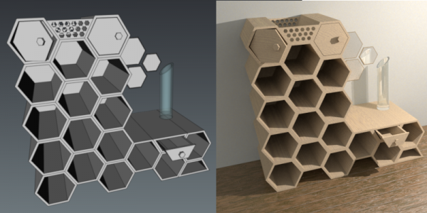
Example by schupin of a 3D model and high quality render produced with FreeCAD and POV-Ray.
The files used in this tutorial are in post #8 in the same thread.
Basic setup
Follow the basic workflow outlined in the Raytracing Workbench documentation.
For direct rendering to work, the povray executable must be set in Edit → Preferences → Raytracing → Render → POV-Ray executable; set it to its location in your system, for example, /usr/bin/povray. Other options used by the renderer can be defined here as well, including the width +W and height +H of the image, and the use of antialiasing +A.
Setup the .pov file
1. Create an assembly using bodies from the Part or PartDesign Workbenches, or any other workbench that produces solid objects, for example, the Arch Workbench. Assign colors or materials to the individual bodies that make the assembly, approximately matching the color that you want in your render.
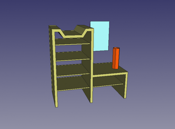
Assembly of three bodies created in FreeCAD, and with colors or materials assigned.
2. If your model is very detailed, make sure the ViewDeviation of the body is set to a low value, between 0.1 and 0.01, or even smaller. The lower this value is, the more detailed the exported mesh will be, and thus the better the quality of the render will be.
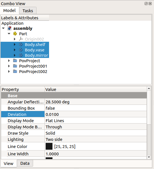
Deviation property of the bodies created in FreeCAD; the deviation needs to be small in order to export the parts with good resolution.
3. Create a POV-Ray project by clicking New. If the viewport is set as orthographic, change it to perspective, as the renderer will normally work with a camera with perspective view. Using perspective view will allow you to see better the type of scene that will be rendered.
4. Select all objects that you want to add to your scene, then select the created PovProject object, and click on InsertPart.
Note: beware of those objects that are not currently visible in the 3D viewport. If they are invisible but are included in the scene, they will still be rendered. On the other hand, if you really want to omit a body from being rendered, don't select it for inclusion into the POV-Ray project.
Note 2: all objects in the POV-Ray project will have a name based on their internal FreeCAD name. It's important to note which is the POV-Ray name, as further options, for example, the material textures, will be assigned to these POV-Ray names.
5. In the 3D viewport, zoom, pan and rotate the view to setup the scene as you want. Make sure the objects are centered in the viewport, then select the created PovProject object, and press ResetCamera.
6. The POV-Ray file is now ready; it contains the selected objects and the camera information. Select the created PovProject object, and then press ExportProject to save the
.pov file.
7. The created .pov file can now be rendered directly from FreeCAD. Select the created PovProject object, then press Render. When the popup image appears on screen, click on it so that it is sent to FreeCAD in its own window tab.
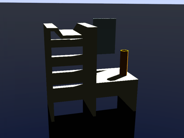
First render of the assembly produced with POV-Ray, with the standard template written by the Raytracing Workbench.
7.1. With the .pov file already created, it is also possible to run povray from the command line.
povray assembly.pov +W800 +H600 +AM2 +A
The options +WX +HY set the horizontal and vertical pixel sizes of the final image.
The options +AM2 (type 2, recursive super-sampling) and +A trigger antialiasing to produce a smoother image.
8. By double clicking the PovProject object it's possible to see that it is using the ProjectStd.pov template; this template creates a basic .pov file which will produce a simple and dark image.
To improve the appearance of the image, use a better template. Double click the PovProject object and choose the RadiosityNormal.pov template. Then export a new .pov file, and run again the renderer. The image should look brighter and generally better.
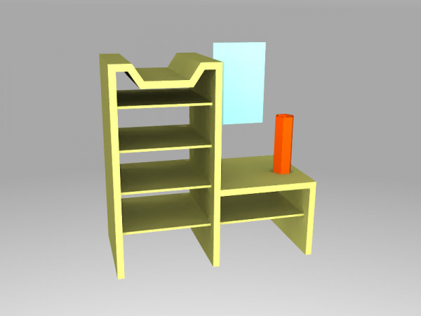
Render of the assembly produced with POV-Ray, with the RadiosityNormal template written by the Raytracing Workbench.
Once again double click the PovProject object and now choose the RadiosityOutdoorHQ.pov template. Then export a new .pov file, and run again the renderer. The image should take longer to produce, but the result should have better quality.
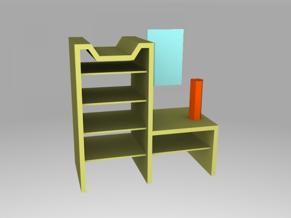
Render of the assembly produced with POV-Ray, with the RadiosityOutdoorHQ template written by the Raytracing Workbench.
If the rendered image is good enough, then it can be saved, and there is nothing more to do. However, in order to control precisely the appearance of the materials and produce even better results, the .pov file needs to be edited manually.
In the following sections, we edit the basic .pov file produced with the ProjectStd template.
Editing the .pov file
9. The .pov file generated by FreeCAD is a simple text file that can be opened with any editor. It loosely resembles a C++ source code file: directives start with a hash # and are terminated by a semi-colon ;. Curly braces { } are used to limit section blocks, and indentation is arbitrary white space. Comments are indicated with a double slash //; block comments can be defined with a pair of /* */, like in C.
The file may look complicated at first but 90% of its content is just mesh data that doesn't require many changes, as these meshes represent the geometry of the bodies that we want to render.
The file is structured as follows:
- Includes
- Global settings
- Sky sphere
- Planes
- Finishes and textures
- Camera
- Mesh and body information
- Light source
The camera information will not be touched, neither most information in the meshes. The main modifications will be made on the other sections.
As the meshes won't be heavily modified, the file can be re-organized so this information is at the end of the file.
This is the complete content of the .pov file, only without the meshes.
// Persistence of Vision Ray Tracer Scene Description File
// for FreeCAD (http://www.freecadweb.org)

#version 3.6;

#include "colors.inc"
#include "metals.inc"

// ----------------------------------------

global_settings {
    assumed_gamma 1.0
    ambient_light color rgb <1.0,1.0,1.0>
    max_trace_level 20
}

// ----------------------------------------


sky_sphere {
  pigment {
    gradient y
    color_map {
      [0.0 rgb <0.6,0.7,1.0>]
      [0.7 rgb <0.0,0.1,0.8>]
    }
  }
}


// ----------------------------------------

plane {
  y, -1
  texture { pigment {rgb <0.0,0.0,0.0>} finish {ambient 0.0 reflection 0.05 specular 0.0} }
}

// Standard finish
//#declare StdFinish = F_MetalA;
//#declare StdFinish = finish { diffuse 0.7 };
//#declare StdFinish = finish { phong 0.5 };
//#declare StdFinish = finish { ambient rgb <0.5,0.5,0.5> };
//#declare StdFinish = finish { crand 0.5 phong 0.9};
#declare StdFinish = finish { ambient 0.01 diffuse 0.9 phong 1.0 phong_size 70 metallic brilliance 1.5} ;

// declares position and view direction

// Generated by FreeCAD (http://www.freecadweb.org/)
#declare cam_location =  <-171.753,1229.11,-2667.08>;
#declare cam_look_at  = <636.959,359.955,160.296>;
#declare cam_sky      = <0.068217,0.958943,0.275273>;
#declare cam_angle    = 45;
camera {
  location  cam_location
  look_at   cam_look_at
  sky       cam_sky
  angle     cam_angle
  right x*800/600
}
// Written by FreeCAD http://www.freecadweb.org/
// face number1 +++++++++++++++++++++++++++++++++++++++++++++++++++++++++++++++++++++
// ... meshes should be defined here until the end of the file ...


//default light
light_source {
  cam_location + cam_angle * 100
  color rgb <10, 10, 10>
}
Basic re-organization
10. Open the .pov file with a text editor, go to the end of the file, select and cut the light_source section, and paste it before the first //face number1 line.
The resulting file should have the camera and light_source sections next to each other, for example
// Generated by FreeCAD (http://www.freecadweb.org/)
#declare cam_location =  <-171.753,1229.11,-2667.08>;
#declare cam_look_at  = <636.959,359.955,160.296>;
#declare cam_sky      = <0.068217,0.958943,0.275273>;
#declare cam_angle    = 45;
camera {
  location  cam_location
  look_at   cam_look_at
  sky       cam_sky
  angle     cam_angle
  right x*800/600
}

//default light
light_source {
  cam_location + cam_angle * 100
  color rgb <10, 10, 10>
}
// Written by FreeCAD http://www.freecadweb.org/
// face number1 +++++++++++++++++++++++++++++++++++++++++++++++++++++++++++++++++++++
.
.
.
Prepare lights
11. By default, the project file defines one light with a position and color.
light_source {
  cam_location + cam_angle * 100
  color rgb <10, 10, 10>
}
The position of the light is defined by a vector <x, y, z>. The color can be established like an <r, g, b> vector or it could also be a named color such as White. If the RGB values are given, they should be in the range 0.0 to 1.0 for the light to have normal brightness.
Like other objects, the light can be modified with many options. The area_light option creates a rectangular source, which is more realistic as it results in diffuse illumination that creates soft shadows. The adaptive keyword helps reduce the computation time of the light paths; the larger the value the more accurate the result will be; to avoid long rendering times you should use the smallest integer that gives an acceptable result (1 or 2 is usually enough); to obtain the best result remove the keyword completely (long rendering time). The jitter keyword helps improve the shadows by randomly shifting the position of the lights. The keywords circular and orient turn the area light into a spherical source, which will produce better shadows when there are rounded objects in the scene. Including fade_distance and fade_power is helpful to attenuate the value of the light with distance, just like it happens with a real light source.
Set up the light coming from the right and above.
light_source {
    <1200, 1000, -1300>
    color White
    area_light <100, 0, 0>, <0, 0, 100>, 20, 20
    adaptive 1
    jitter
    circular orient
    fade_distance 1000 fade_power 2
}
If the light source is supposed to be in the scene, it may be useful to see a reference on the screen where this source should be. To this effect, create a sphere of a small radius and assume this sphere represents the light source; position the sphere where you want, then move the light very close to these coordinates, and test the lighting of the scene; when you are satisfied with the position of the light, simply delete the sphere.
sphere {
    <1200, 1000, -1200>, 10
    pigment { color White }
}
12. The sky_sphere section is used to create a realistic sky background. It is commonly defined as a gradient and a color_map of at least two colors in order to produce a smooth transition from the color of the horizon to the color of the zenith of the scene.
sky_sphere {
    pigment {
        gradient y
        color_map {
            [0.0 color Gray50]
            [0.7 color White]
        }
    }
}
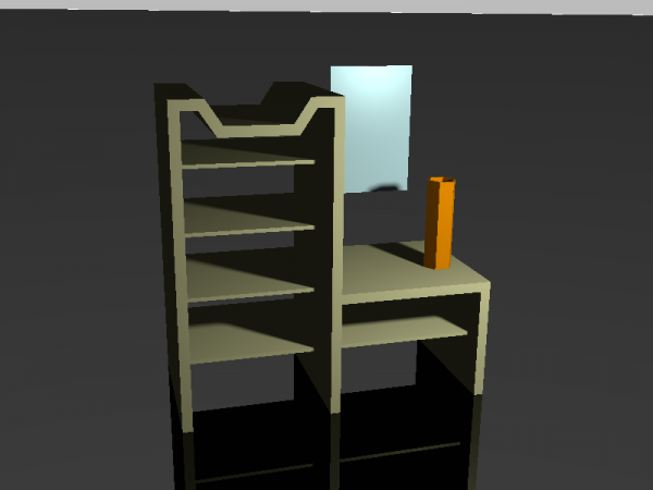
Starting from the standard template, render of the scene with POV-Ray, with the light source and sky sphere set up.
Prepare the body textures
13. The textures of each body need to be adjusted. This is the most time-consuming job of this process.
In the .pov file each body is described in this way
- Face1, Face2, Face3, Face4, ...
- Body (union of faces)
- Object
A body mesh is defined by faces, and each face is defined by a series of triangular elements that themselves are defined by vertex_vectors, normal_vectors, and face_indices. This information doesn't need to be modified at all. Then, each body is defined as the union of the specified faces. Again, this information doesn't need modification.
Finally, each object to be rendered is defined as one of the specified bodies, with a particular texture, which itself is defined by properties like pigment and finish.
// instance to render
object {Pov_Body
 texture {
      pigment {color rgb <0.827451,0.827451,0.431373>}
      finish {StdFinish } //definition on top of the project
  }
}
By searching the .pov file for the keyword object, it's possible to go directly to the desired part in the file, and modify its texture appropriately.
As indicated in the comment, the definition of StdFinish is at the top of the file, in this case before the camera information. This value can be declared in many ways, as a combination of different properties, as shown in the commented and uncommented lines.
// Standard finish
//#declare StdFinish = F_MetalA;
//#declare StdFinish = finish { diffuse 0.7 };
//#declare StdFinish = finish { phong 0.5 };
//#declare StdFinish = finish { ambient rgb <0.5,0.5,0.5> };
//#declare StdFinish = finish { crand 0.5 phong 0.9};
#declare StdFinish = finish { ambient 0.01 diffuse 0.9 phong 1.0 phong_size 70 metallic brilliance 1.5} ;
In general, a texture is a container that describes a material; it includes information like the pigment (color or graphic), normal (how the color changes with the curvature of the surface), finish (interaction of the surface with the light), pattern (agate, brick, dents, leopard, radial, ripples, tiling, waves, wood, etc.), and other properties. There are many options that can be combined together to produce a texture. This mixing is not trivial, but there are many examples online to obtain the desired appearance of the material.
Material libraries
14. POV-Ray comes with an extensive library of materials that can be used by name. By default, the project template makes available some materials by using #include statements at the beginning of the file. These materials can be further modified as desired.
#include "colors.inc"
#include "metals.inc"
The library colors.inc defines basic colors by name, Red, Green, Blue, Yellow, Cyan, Magenta, Clear, White, and Black. It also defines several other shades as well as functions to transform colors. The library metals.inc contains copper, silver, chrome, and brass textures, and golds.inc contains the gold textures.
The standard libraries are located in the installation directory of POV-ray, for example
/usr/share/povray-3.7/include/
New textures
15. For example, to create a mirror texture, the finish is given a high value of reflection.
#declare T_mirror = texture {
    finish { reflection {0.9} }
}
Alternatively, for metals, a predefined finish can be used.
#include "metals.inc"
#declare T_mirror = texture {
    finish { F_MetalE }
}
Then it can be assigned to the specific object.
object {Pov_Body002
    texture { T_mirror }
}
The woods.inc library defines the T_Wood7 texture (yellow pine, ragged grain). It can be used as the basis of a more complex texture, with some additional scaling and translation.
#include "woods.inc"
#declare T_wood = texture {
    T_Wood7
    scale 50.0
    translate x*1
    translate y*10
}
Then it is assigned to the specific object.
object {Pov_Body
    texture { T_wood }
}
The glass.inc library defines F_Glass2 as a finish for transparent acrylic; it also defines I_Glass as an interior material which, together with the caustics option, is used to calculate as close as possible the effects of light passing through a transparent material. In this case, the material section is used, containing external (texture) and internal (interior) information of the material.
#declare M_vase = material {
    texture {
        pigment { color rgbf <1.0, 0.73333, 0.0, 0.75> }
        finish { F_Glass2 }
    }
    interior { I_Glass caustics 1.0 }
}
Then it is assigned to the specific object.
object {Pov_Body001
    material { M_vase }
}
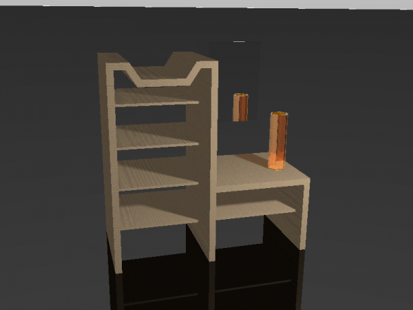
Starting from the standard template, render of the scene with POV-Ray, with the light source and sky sphere set up, and materials assigned.
Prepare planes
16. If not provided by the original 3D model, planes can be added to simulate a floor or table top on which the objects are standing. More planes can be defined to serve as walls or other types of boundaries.
By default, a single plane is created. It is placed 1 millimeter below the model, so that it appears as a floor. The plane is assigned a basic texture that is black and slightly reflective.
plane {
  y, -1
  texture { pigment {rgb <0.0,0.0,0.0>} finish {ambient 0.0 reflection 0.05 specular 0.0} }
}
Notice that in POV-Ray the X axis is defined as horizontal (left-right), the Y axis is defined as vertical (up-down), and the Z axis is defined as depth (front-rear).
For a simple gray floor, that is barely reflective use
plane {
  y, -1
  texture { pigment {rgb <0.3, 0.3, 0.3>} finish {ambient 0.0 reflection 0.01 specular 0.0} }
}
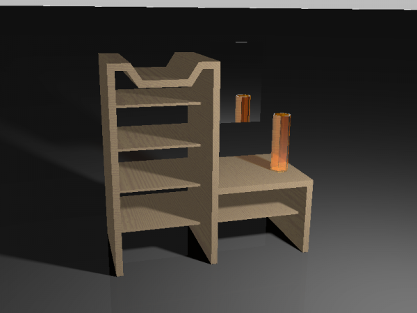
Starting from the standard template, render of the scene with POV-Ray, with the light source and sky sphere set up, materials assigned, and a floor plane with a basic gray texture.
17. The plane can be given a more complex appearance with the help of normals and material libraries.
Define a normal map that will be used to give the plane the appearance of a parquet floor.
#declare Parquet_normal = normal {
    gradient z 2 slope_map { [0 <0,1>][0.05 <1,0>][0.95 <1,0>][1 <0,-1>] }
    scale 80
} ;
Then define the plane. As pigment use a wood color_map defined in woods.inc, and modify it with turbulence and scale so that the wood grain looks random. Then add the created normal, together with another normal; this will result in the texture of the parquet with slight imperfections. Then as finish, make it a little bit reflective and glossy.
#include "woods.inc"
plane {
    y, -1
    pigment {
        wood color_map { M_Wood8A }
        turbulence 0.5 scale <10, 1, 1>*20
    }
    normal {
        average normal_map {
          [1 Parquet_normal]
          [1 wood 0.5 slope_map { [0 <0,0>][0.5 <0.5,1>][1 <1,0>] }
              turbulence 0.5 scale <10, 1, 1>*20]
        }
    }
    finish { ambient 0.0 reflection 0.1 specular 0.2 }
}
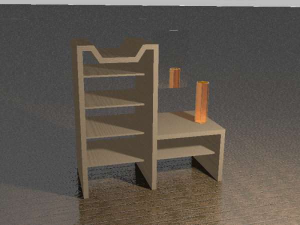
Starting from the standard template, render of the scene with POV-Ray, with the light source and sky sphere set up, materials assigned, and a floor plane with a parquet texture.
18. Add a second plane, this time perpendicular to the Z direction, to serve as a backwall. Displace it just a little bit behind the model to avoid covering the mirror. Include the stones.inc library, add a generic granite texture, and scale it a bit. This will result in the appearance off a simple dry wall.
#include "stones.inc"
plane {
    z, 10
    texture {
        T_Grnt1
        scale 0.02
    }
}
A third plane can be added behind the position of the camera so that the mirror reflects a limited area between the two walls.
#include "stones.inc"
plane {
    z, -3700
    texture {
        T_Grnt1
        scale 0.02
    }
}
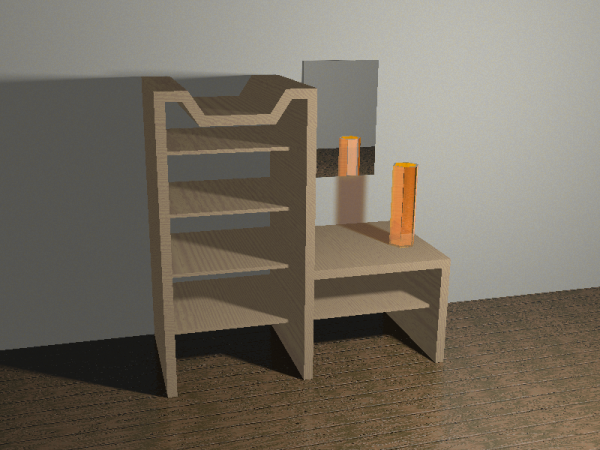
Starting from the standard template, render of the scene with POV-Ray, with the light source and sky sphere set up, materials assigned, a floor plane with a parquet texture, and back walls with drywall textures.
Prepare the global settings, radiosity
19. The global settings define ambient light.
global_settings {
    assumed_gamma 1.0
    ambient_light color rgb <1.0,1.0,1.0>
    max_trace_level 20
}
The radiosity property inside the global_settings controls the way POV-Ray computes diffuse light interactions between different objects. It's essential to adjust this property to obtain good rendering results.
Because it can be time consuming to test different radiosity settings you can use a variable Rad_Quality and a #switch statement to quickly set low, medium or high quality render settings. The higher the quality settings the more time is required to render an image.
#declare Rad_Quality = 1;

global_settings {
    assumed_gamma 1.0
    ambient_light color rgb <1.0,1.0,1.0>
    max_trace_level 20

#switch (Rad_Quality)
 #case (1)
    radiosity { // Settings 1 (fast)
        pretrace_start 0.08
        pretrace_end   0.02
        count 50
        error_bound 0.5
        recursion_limit 1
    }
    #break
 #case (2)
    radiosity { // Settings 2 (medium quality)
        pretrace_start 0.08
        pretrace_end   0.01
        count 120
        error_bound 0.25
        recursion_limit 1
    }
    #break
 #case (3)
    radiosity { // Settings 3 (high quality)
        pretrace_start 0.08
        pretrace_end   0.005
        count 400
        error_bound 0.1
        recursion_limit 2
    }
    #break
#end
}
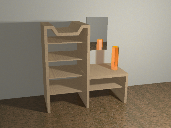
Starting from the standard template, render of the scene with POV-Ray, with the light source and sky sphere set up, materials assigned, a floor plane with a parquet texture, and back walls with drywall textures. Radiosity settings for fast rendering.
20. The rad_def.inc library defines a macro to quickly set up the radiosity to a predefined configuration.
#include "rad_def.inc"
global_settings {
    radiosity {
        Rad_Settings(Setting, Normal, Media)
    }
}
The Setting value can be one of the predefined constants:
Radiosity_Default
Radiosity_Debug
Radiosity_Fast
Radiosity_Normal
Radiosity_2Bounce
Radiosity_Final
Radiosity_OutdoorLQ
Radiosity_OutdoorHQ
Radiosity_OutdoorLight
Radiosity_IndoorLQ
Radiosity_IndoorHQ
The Normal and Media values are either off or on.
Therefore, to test different settings, the #switch statement could also be written like in the following.
#declare Rad_Quality = 3;

global_settings {
    assumed_gamma 1.0
    ambient_light color rgb <1.0,1.0,1.0>
    max_trace_level 20

#switch (Rad_Quality)
 #case (1)
    radiosity { // Settings 1 (fast)
        Rad_Settings(Radiosity_Fast, off, off)
    }
    #break
 #case (2)
    radiosity { // Settings 2 (medium quality)
        Rad_Settings(Radiosity_2Bounce, on, on)
    }
    #break
 #case (3)
    radiosity{ // Settings 3 (high quality)
        Rad_Settings(Radiosity_Final, on, on)
        recursion_limit 2
    }
    #break
#end
}
The exact values used by these presets can be found in the rad_def.inc file which is found in the installation directory of POV-Ray, for example:
/usr/share/povray-3.7/include/
The Raytracing Workbench has three default templates:
ProjectStd.pov, it doesn't useradiosityat all.RadiosityNormal.pov, it uses the presetRadiosity_Normal.RadiosityOutdoorHQ.pov, it uses the presetRadiosity_OutdoorHQ.
Final render
21. The edited .pov file can be saved when all adjustments have been done.
The final structure is as follows:
- Includes, with additional libraries
- Global settings, with radiosity parameters
- Sky sphere, with lighter color
- Planes, positioned and with textures
- Finishes and textures, with custom definitions
- Camera, not changed
- Light source, with additional properties
- Mesh and body information, using the textures defined previously
Note: the sections of the .pov file can be in any order, although it is probably easier to work with the file if the mesh information is at the end.
The final rendering can be done by clicking Render or by running the executable from the command line.
povray assembly.pov +W800 +H600 +AM2 +A
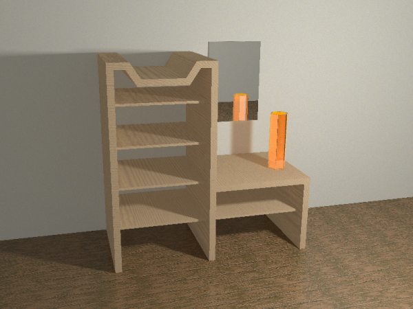
Starting from the standard template, render of the scene with POV-Ray, with the light source and sky sphere set up, materials assigned, a floor plane with a parquet texture, and back walls with drywall textures. Radiosity settings for high quality result: Radiosity_Final and recursion_limit 2.
This is the complete content of the .pov file, only without the last section, that is, without the meshes.
// Persistence of Vision Ray Tracer Scene Description File
// for FreeCAD (http://www.freecadweb.org)

#version 3.6;

#include "colors.inc"
#include "metals.inc"
#include "woods.inc"
#include "glass.inc"
#include "stones.inc"
#include "rad_def.inc"

// ----------------------------------------
#declare Rad_Quality = 3;

global_settings {
    assumed_gamma 1.0
    ambient_light color rgb <1.0,1.0,1.0>
    max_trace_level 20

#switch (Rad_Quality)
 #case (1)
    radiosity { // Settings 1 (fast)
        Rad_Settings(Radiosity_Fast, off, off)
    }
    #break
 #case (2)
    radiosity { // Settings 2 (medium quality)
        Rad_Settings(Radiosity_2Bounce, on, on)
    }
    #break
 #case (3)
    radiosity{ // Settings 3 (high quality)
        Rad_Settings(Radiosity_Final, on, on)
        recursion_limit 2
    }
    #break
#end
}

// ----------------------------------------


sky_sphere {
    pigment {
        gradient y
        color_map {
            [0.0 color Gray50]
            [0.7 color White]
        }
    }
}


// ----------------------------------------

#declare Parquet_normal = normal {
    gradient z 2 slope_map { [0 <0,1>][0.05 <1,0>][0.95 <1,0>][1 <0,-1>] }
    scale 80
} ;

// Floor
plane {
    y, -1
    pigment {
        wood color_map { M_Wood8A }
        turbulence 0.5 scale <10, 1, 1>*20
    }
    normal {
        average normal_map {
          [1 Parquet_normal]
          [1 wood 0.5 slope_map { [0 <0,0>][0.5 <0.5,1>][1 <1,0>] }
              turbulence 0.5 scale <10, 1, 1>*20]
        }
    }
    finish { ambient 0.0 reflection 0.1 specular 0.2 }
}

// Back wall
plane {
    z, 10
    texture {
        T_Grnt1
        scale 0.02
    }
}

// Behind camera wall
plane {
    z, -3700
    texture {
        T_Grnt1
        scale 0.02
    }
}

#declare T_mirror = texture {
    finish { reflection {0.9} }
//    finish { F_MetalE }
}

#declare T_wood = texture {
    T_Wood7
    scale 50.0
    translate x*1
    translate y*10
}

#declare M_vase = material {
    texture {
        pigment { color rgbf <1.0, 0.73333, 0.0, 0.75> }
        finish { F_Glass2 }
    }
    interior { I_Glass caustics 1.0 }
}
// declares position and view direction

// Generated by FreeCAD (http://www.freecadweb.org/)
#declare cam_location =  <-171.753,1229.11,-2667.08>;
#declare cam_look_at  = <636.959,359.955,160.296>;
#declare cam_sky      = <0.068217,0.958943,0.275273>;
#declare cam_angle    = 45;
camera {
  location  cam_location
  look_at   cam_look_at
  sky       cam_sky
  angle     cam_angle
  right x*800/600
}
//default light
light_source {
    <1200, 1000, -1300>
    color White
    area_light <100, 0, 0>, <0, 0, 100>, 20, 20
    adaptive 1
    jitter
    circular orient
    fade_distance 1000 fade_power 2
}
// Written by FreeCAD http://www.freecadweb.org/
// face number1 +++++++++++++++++++++++++++++++++++++++++++++++++++++++++++++++++++++
// ... meshes should be defined here until the end of the file ...
Final notes
POV-Ray is a relatively old piece of software, first released in the early 1990s. Its main advantages over more modern software are
- it is a tested solution that has existed for many years
- runs in many operating systems
- the scene can be set with only one text file
- requires simple computational resources to produce a high quality image, so it works even in relatively old hardware
The user is advised to read the POV-Ray documentation and more tutorials or examples in order to get the right settings for his or her needs.
- Getting started
- Installation: Download, Windows, Linux, Mac, Additional components, Docker, AppImage, Ubuntu Snap
- Basics: About FreeCAD, Interface, Mouse navigation, Selection methods, Object name, Preferences, Workbenches, Document structure, Properties, Help FreeCAD, Donate
- Help: Tutorials, Video tutorials
- Workbenches: Std Base, Arch, Assembly, CAM, Draft, FEM, Inspection, Mesh, OpenSCAD, Part, PartDesign, Points, Reverse Engineering, Robot, Sketcher, Spreadsheet, Surface, TechDraw, Test Framework
- Hubs: User hub, Power users hub, Developer hub