PartDesign Examples/fr: Difference between revisions
(Created page with "'''Galerie'''") |
(Created page with "=== Objets à balayage circulaire ===") |
||
| Line 79: | Line 79: | ||
<div class="mw-collapsible-content toccolours"> |
<div class="mw-collapsible-content toccolours"> |
||
=== |
=== Objets à balayage circulaire === |
||
{|{{Prettytable|width: 200mm}} |
{|{{Prettytable|width: 200mm}} |
||
Revision as of 19:00, 23 March 2022
Cette documentation n'est pas terminée. Merci de nous aider et de contribuer à la documentation.
Modèle GuiCommand explique comment les commandes doivent être documentées. Parcourez Category:UnfinishedDocu pour voir d'autres pages incomplètes comme celle-ci. Voir Category:Command_Reference pour toutes les commandes.
Voir Écrire une page Wiki pour apprendre à éditer les pages du wiki, et aller à Contribuer à FreeCAD pour apprendre d'autres façons de contribuer.Introduction
Parfois, vous avez besoin d'un indice de la puissance d'un outil, sans trop d'explications.
Il s'agit d'une série d'exemples qui peuvent être réalisés avec certains outils. Pour des explications détaillées, consultez les descriptions des outils et cherchez des tutoriels sur le web.
Protrusion
PartDesign Protrusion est un outil permettant de créer des objets Protrusion, qui sont des objets prismatiques tels que des objets d'extrusion, des cylindres, des cônes, des cubes, des coins, des sphères...
Chaque objet est basé sur un contour (jaune), qui définit la forme de la section transversale (de préférence réalisé avec l'atelier Sketcher).
Le contour est tiré le long d'une direction (extrudé) pour donner à l'objet une épaisseur ou une longueur.
Par défaut, il s'agit de la direction normale du plan contenant le contour (plan d'esquisse). Il est possible, en option, de modifier la direction en éditant les paramètres dans le panneau des propriétés ou en sélectionnant une ligne droite séparée (blanche).
Galerie
Primitives prismatiques
| Cylindre | 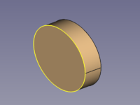
|
|
| Cube | 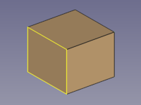
|
|
| Cuboïde | 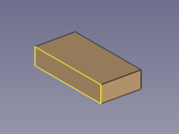
|
|
| Prisme régulier | 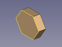
|
|
| Pyramide tronquée | 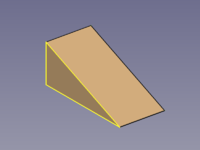
|
|
Profils prismatiques
Balayage additif
PartDesign Balayage additif est un outil permettant de créer des objets AdditivePipe tels que des objets de balayage, des objets d'extrusion, des objets de rotation, des cylindres, des cônes, des cubes, des pyramides, des sphères...
Chaque objet est basé sur au moins deux lignes (réalisées de préférence avec l'atelier Sketcher) :
- Un contour (jaune), pour définir la forme de la section transversale.
- Un chemin (blanc), pour le balayer.
Il n'est pas difficile de réaliser que certains objets peuvent également être créés avec d'autres outils, mais auriez-vous deviné la polyvalence de cet outil sans ces exemples ?
Galerie
Objets à balayage circulaire
| Sphere | 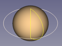
|
|
| Sphere Segment | 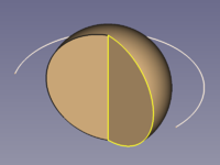
|
|
| Hemisphere | 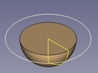
|
|
| Torus | 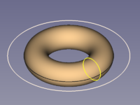
|
|
| Cone | 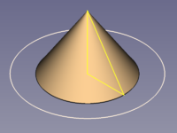
|
|
| Cylinder | 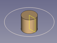
|
|
| Pipe Hollow Cylinder |
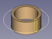
|
|
Prismatic Objects
Straight Sweep Objects
| Cylinder | 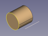
|
|
| Cube | 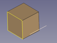
|
|
| Cuboid | 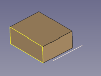
|
|
| Wedge | 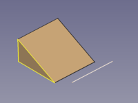
|
|
| Regular Prism | 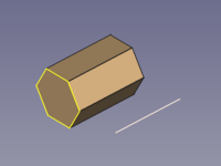
|
|
| Star-shaped Prism | 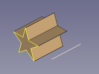
|
|
| Double-T Beam | 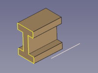
|
|
Conical Objects
| Cone | 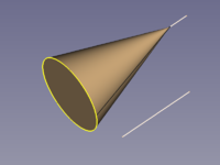
|
|
| Pyramid | 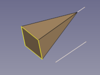
|
|
| Tilted Pyramid | 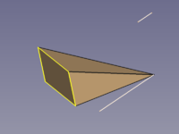
|
|
Curved Sweep Objects
| Hose (Pipe) |
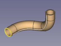
|
|
| Square Pipe | 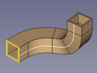
|
|
| Wire | 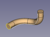
|
|
| Horn | 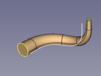
|
|
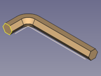
| Legendary Hex-Wrench |
|
|
Spiral and Helical Objects
| Coil Spring | 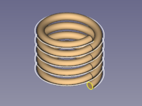
|
|
| Hairspring Balance Spring |
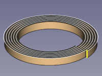
|
|
| Volute Spring, Conical Spring |
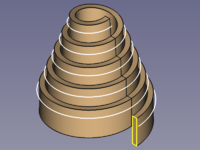
|
|
Transition Objects
| Square to Circle via path |
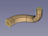
|
|
| Square to Circle direct |
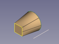
|
|
| Polygon to Star | 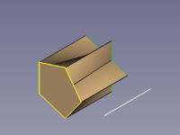
|
|
Options
Corner Transition
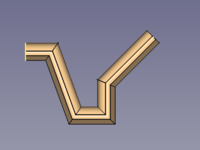
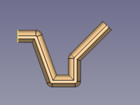
A polyline can be used as a path, and the property Transition influences the shapes of the corners.
Transformed needs special attention as it can produce flat areas where the thickness is 0.
| Parameter | Iso View | Top View |
|---|---|---|
| Transformed | 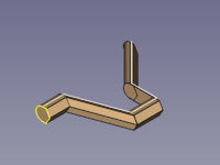
|
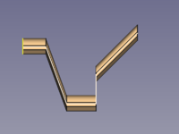
|
| Right corner | 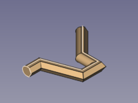
|
|
| Round corner | 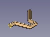
|
|
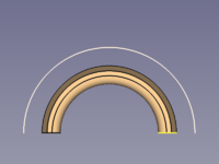
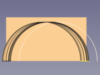
Orientation Mode
| Parameter | Iso View | Top View |
|---|---|---|
| Standard | 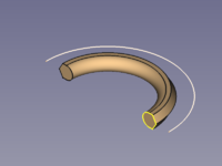
|
|
| Fixed | 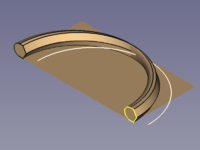
|
|
| Frenet | 
|

|
| Auxiliary | ||
| Binormal |