Measurement Of Angles On Holes/fr: Difference between revisions
No edit summary |
(Updating to match new version of source page) |
||
| Line 31: | Line 31: | ||
{{Caption|Ci-dessus : création avec [[File:TechDraw 2LineCenterLine.svg|16px]] d'un trait d'axe entre 2 lignes}} |
{{Caption|Ci-dessus : création avec [[File:TechDraw 2LineCenterLine.svg|16px]] d'un trait d'axe entre 2 lignes}} |
||
<!--T:12--> |
|||
In the dialog box choice "Ausgerichtet / Aligned" for achses out of main achses. "Erweitert um / Extend by" means the length of the center line beyond of the body line in the drawing. With "Shift Horiz." and "Shift Vert." the center line can move in horizontal or vertical direction, if is necessary. "Stil" means the figure of center line. |
In the dialog box choice "Ausgerichtet / Aligned" for achses out of main achses. "Erweitert um / Extend by" means the length of the center line beyond of the body line in the drawing. With "Shift Horiz." and "Shift Vert." the center line can move in horizontal or vertical direction, if is necessary. "Stil" means the figure of center line. |
||
<!--T:13--> |
|||
[[Image:AnHi7.PNG|250px|left]] |
[[Image:AnHi7.PNG|250px|left]] |
||
<br> |
<br> |
||
| Line 54: | Line 52: | ||
{{Caption|Above: dialog box}} |
{{Caption|Above: dialog box}} |
||
<!--T:14--> |
|||
The created center line is fix and can didn't change! Delete only with [[Image:AnHi9.PNG|24px]] from the tool bar after selecting the center line. |
The created center line is fix and can didn't change! Delete only with [[Image:AnHi9.PNG|24px]] from the tool bar after selecting the center line. |
||
<br> |
<br> |
||
<br> |
<br> |
||
<!--T:30--> |
|||
2. Setting angles: |
2. Setting angles: |
||
<!--T:31--> |
|||
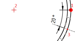
Quadrant points select with [[Image:AnHi10.PNG|24px]] from the tool bar. Next select the points as show below and use [[Image:AnHi8.PNG|24px]] from the tool bar to create the angle. Other succession create other angles. |
Quadrant points select with [[Image:AnHi10.PNG|24px]] from the tool bar. Next select the points as show below and use [[Image:AnHi8.PNG|24px]] from the tool bar to create the angle. Other succession create other angles. |
||
Is there no catching point on the center line change "ISO count" in the properties. |
Is there no catching point on the center line change "ISO count" in the properties. |
||
<!--T:32--> |
|||
[[Image:AnHi11.PNG|250px|left]] |
[[Image:AnHi11.PNG|250px|left]] |
||
<br> |
<br> |
||
| Line 76: | Line 70: | ||
{{Caption|Above: Succession of selection|center}} |
{{Caption|Above: Succession of selection|center}} |
||
{{TechDraw Tools navi{{#translation:}}}} |
{{TechDraw Tools navi{{#translation:}}}} |
||
{{Tutorials navi{{#translation:}}}} |
{{Tutorials navi{{#translation:}}}} |
||
Revision as of 10:37, 10 April 2020
| Thème |
|---|
| TechDraw |
| Niveau |
| Base |
| Temps d'exécution estimé |
| 1 minute |
| Auteurs |
| AnHi |
| Version de FreeCAD |
| 0.19 |
| Fichiers exemples |
| None |
| Voir aussi |
| None |
Introduction
Ce didacticiel explique comment créer des lignes de perçage centrales à l'aide de l'atelier TechDraw avec des trous orientés.
En créant des angles pour les trous, il n'est pas possible d'utiliser des lignes médianes verticales ou horizontales (false/true) à partir des propriétés de la vue. Pour cette nécessité des lignes guides et/ou des points guides sont créés.
Processus
1. Définir des axes sur les trous :
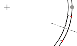
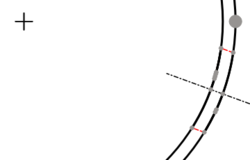
Il existe diverses possibilités pour créer une ligne médiane sur des trous. En premier, les lignes ou les points du trou doivent être sélectionnés comme indiqué ci-dessous. Ensuite, les outils suivants peuvent être utilisés à partir de la barre d'outils pour créer la ligne médiane :
Ci-dessus : création avec d'un trait d'axe entre 2 points
Ci-dessus : création avec d'un trait d'axe entre 2 lignes
In the dialog box choice "Ausgerichtet / Aligned" for achses out of main achses. "Erweitert um / Extend by" means the length of the center line beyond of the body line in the drawing. With "Shift Horiz." and "Shift Vert." the center line can move in horizontal or vertical direction, if is necessary. "Stil" means the figure of center line.

Above: dialog box
The created center line is fix and can didn't change! Delete only with File:AnHi9.PNG from the tool bar after selecting the center line.
2. Setting angles:
Quadrant points select with File:AnHi10.PNG from the tool bar. Next select the points as show below and use File:AnHi8.PNG from the tool bar to create the angle. Other succession create other angles. Is there no catching point on the center line change "ISO count" in the properties.

Above: Succession of selection
- Pages : Page par défaut, Page à partir d'un modèle, Redessiner une page, Tout imprimer
- Vues : Vue, Vue active, Groupe de projections, Vue en coupe, Vue en coupe complexe, Vue détaillée, Vue d'un objet Draft, Vue d'un objet Arch, Vue d'un objet Spreadsheet, Fenêtre de rognage, Copier une vue, Projection de forme
- Empilement : Empiler en haut, Empiler en bas, Empiler vers le haut, Empiler vers le bas
- Décorations : Hachures par motif, Hachures géométriques, Symbole, Image, Bascule des cadres
- Cotes : Cote de longueur, Cote horizontale, Cote verticale, Cote de rayon, Cote de diamètre, Cote angulaire, Cote angulaire par 3 points, Cote étendue horizontale, Cote étendue verticale, Lier une cote, Infobulle, Cote axonométrique, Cote à partir des points du repère, Réparation des cotes
- Annotations : Annotation, Ligne de référence, Annotation texte enrichi, Point cosmétique, Points médians, Sommets quadrants, Ligne centrale à une face, Ligne centrale entre 2 lignes, Ligne centrale entre 2 points, Ligne cosmétique par 2 points, Cercle cosmétique, Apparence des lignes, Montrer tout, Soudure, Symbole d'état de surface, Tolérance de trou/d'arbre
- Extensions :
- Attributs et modifications : Sélection des attributs, Modification des attributs, Prolonger, Raccourcir, Verrouiller/déverrouiller, Position d'une vue en coupe, Aligner horizontalement, Aligner verticalement, Aligner obliquemement, Cascade horizontale, Cascade verticale, Cascade oblique, Calculer l'aire des faces sélectionnées, Calculer la longueur d'arc d'arêtes sélectionnées, Personnaliser le format d'infobulle
- Lignes centrales, filetage et taraudage : Axes de centrage, Axes de centrage de trous/vis, Corps de taraudage, Taraudage, Corps de filetage, Filetage, Intersection de lignes, Ajouter un sommet décalé, Cercle, Arc, Cercle par 3 points, Ligne parallèle, Ligne perpendiculaire
- Cotes : Cotes horizontales, Cotes verticales, Cotes obliques, Cotes parallèles horizontales, Cotes parallèles verticales, Cotes parallèles obliques, Cote horizontale chanfrein, Cote verticale chanfrein, Longueur d'arc, Diamètre '⌀', Section tube '〼', Supprimer les symboles, Plus de décimales, Moins de décimales
- Exportation : Exporter au format SVG, Exporter au format DXF
- Fonctions supplémentaires : Groupe de lignes, Modèles, Hachures, Dimensionnement géométrique et tolérance, Préférences
- Démarrer avec FreeCAD
- Installation : Téléchargements, Windows, Linux, Mac, Logiciels supplémentaires, Docker, AppImage, Ubuntu Snap
- Bases : À propos de FreeCAD, Interface, Navigation par la souris, Méthodes de sélection, Objet name, Préférences, Ateliers, Structure du document, Propriétés, Contribuer à FreeCAD, Faire un don
- Aide : Tutoriels, Tutoriels vidéo
- Ateliers : Std Base, Arch, Assembly, CAM, Draft, FEM, Inspection, Mesh, OpenSCAD, Part, PartDesign, Points, Reverse Engineering, Robot, Sketcher, Spreadsheet, Surface, TechDraw, Test

