Manual:Crearea și manipularea geometriei
- Introducere
- Descoperind FreeCAD
- Lucrul cu FreeCAD
- Programarea prin script Python
- Comunitatea
În capitolele anterioare, am aflat despre diferitele ateliere de lucru ale FreeCAD și despre modul în care fiecare dintre ele implementează propriile instrumente și tipuri de geometrii. Același concept se aplică atunci când lucrați din codul Python.
De asemenea, am văzut că marea majoritate a atelierelor de lucru FreeCAD depind de una foarte fundamentală: Workbench Part. De fapt, multe alte ateliere de lucru, cum ar fi Draft și Arch, fac exact ceea ce vom face în acest capitol: utilizează codul Python pentru a crea și manipula geometria pieselor.
Deci, primul lucru pe care trebuie să-l facem pentru a lucra cu geometria pieselor, este de a face Python echivalentă cu comutarea la Workbench Part: import modulul Part:
import Part
Luați un minut pentru a explora conținutul Atelierului Part (Workbench), tastând Part și navigând prin diferitele metode propuse aici. Atelierul Piese (Part) oferă mai multe funcții de comode, cum ar fi makeBox, makeCircle, etc ... care vor construi instantaneu un obiect pentru tine. Încercați aceasta, de exemplu:
Part.makeBox(3,5,7)
Când apăsați Enter după introducerea liniei de mai sus, în vizualizarea 3D nu va apărea nimic, dar ceva similar va fi tipărit pe consolă Python:
<Solid object at 0x5f43600>
Aici intră în scenă un concept important. Ceea ce am creat aici este o Formă de Piesă Acesta nu este un document obiect al FreeCAD (nu încă). În FreeCAD, obiectele și geometria lor sunt independente. Gândiți-vă la un document obiect al FreeCAD ca la un container, care va găzdui o formă. Obiectele parametrice vor avea de asemenea proprietăți precum Lungime și Lățime și vor recalculate forma lor din zbor, ori de câte ori se schimbă una dintre proprietăți. Ceea ce am făcut aici este de a calcula manual o formă.
Acum putem crea cu ușurință un document obiect "generic" în documentul curent (asigurați-vă că aveți cel puțin un nou document deschis) și dați-i o formă de cutie așa cum am și făcut-o:
boxShape = Part.makeBox(3,5,7)
myObj = FreeCAD.ActiveDocument.addObject("Part::Feature","MyNewBox")
myObj.Shape = boxShape
FreeCAD.ActiveDocument.recompute()
Note how we handled myObj.Shape , notice that it is done exactly like we did it in the previous chapter, when we changed other properties of an object, such as box.Height = 5 . In fact, Shape is also a property, just like Height. Only it takes a Part Shape, not a number. In the next chapter we will have a better look at how these parametric objects are constructed.
For now, let's explore our Part Shapes in more detail. At the end of the chapter about [Manual:Traditional modeling, the CSG way|traditional modeling with the Part Workbench] we showed a table that explains how Part Shapes are constructed, and their different components (Vertices, edges, faces, etc). The exact same components exist here and can be retrieved from Python. Part Shapes always have the following attributes: Vertexes, Edges, Wires, Faces, Shells and Solids. All of them are lists, that can contain any number of elements or be empty:
print(boxShape.Vertexes)
print(boxShape.Edges)
print(boxShape.Wires)
print(boxShape.Faces)
print(boxShape.Shells)
print(boxShape.Solids)
For example, let's find the area of each face of our box shape above:
for f in boxShape.Faces:
  print(f.Area)
Or, for each edge, its start point and end point:
for e in boxShape.Edges:
  print("New edge")
  print("Start point:")
  print(e.Vertexes[0].Point)
  print("End point:")
  print(e.Vertexes[1].Point)
As you see, if our boxShape has a "Vertexes" attribute, each Edge of the boxShape also has a "Vertexes" attribute. As we can expect, the boxShape will have 8 vertices, while the edge will only have 2, which are both part of the list of 8.
We can always check what is the type of a shape:
print(boxShape.ShapeType)
print(boxShape.Faces[0].ShapeType)
print(boxShape.Vertexes[2].ShapeType)
So to resume the topic of Part Shapes: Everything starts with Vertices. With one or two vertices, you form an Edge (full circles have only one vertex). With one or more Edges, you form a Wire. With one or more closed Wires, you form a Face (the additional Wires become "holes" in the Face). With one or more Faces, you form a Shell. When a Shell is fully closed (watertight), you can form a Solid from it. And finally, you can join any number of Shapes of any types together, which is then called a Compound.
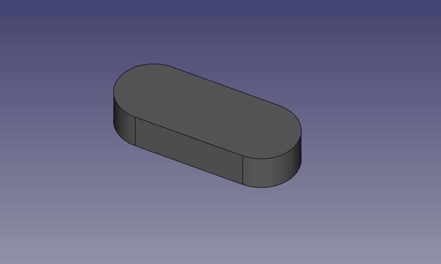
We can now try creating complex shapes from scratch, by constructing all their components one by one. For example, let's try to create a volume like this:
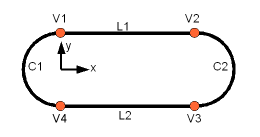
We will start by creating a planar shape like this:
First, let's create the four base points:
V1 = FreeCAD.Vector(0,10,0)
V2 = FreeCAD.Vector(30,10,0)
V3 = FreeCAD.Vector(30,-10,0)
V4 = FreeCAD.Vector(0,-10,0)
Then we can create the two linear segments:
L1 = Part.Line(V1,V2)
L2 = Part.Line(V4,V3)
Note that we didn't need to create Vertices. We could immediately create Part.Lines from FreeCAD Vectors. This is because here we haven't created Edges yet. A Part.Line (as well as Part.Circle, Part.Arc, Part.Ellipse or Part.BSpline) does not create an Edge, but rather a base geometry on which an Edge will be created. Edges are always made from such a base geometry, which is stored in its Curve attribute. So if you have an Edge, doing:
print(Edge.Curve)
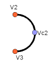
will show you what kind of Edge it is, i.e. if it's based on a line, an arc, etc... But let's come back to our exercise, and build the arc segments. For this, we will need a third point, so we can use the convenient Part.Arc, which takes 3 points:
VC1 = FreeCAD.Vector(-10,0,0)
C1 = Part.Arc(V1,VC1,V4)
VC2 = FreeCAD.Vector(40,0,0)
C2 = Part.Arc(V2,VC2,V3)
Now we have 2 lines (L1 and L2) and 2 arcs (C1 and C2). We need to turn them into edges:
E1 = Part.Edge(L1)
E2 = Part.Edge(L2)
E3 = Part.Edge(C1)
E4 = Part.Edge(C2)
Alternatively, base geometries also have a toShape() function that do exactly the same thing:
E1 = L1.toShape()
E2 = L2.toShape()
...
Once we have a series of Edges, we can now form a Wire, by giving it a list of Edges. We do need to take care of the order.
W = Part.Wire([E1,E4,E2,E3])
And we can check if our Wire was correctly understood, and that it is correctly closed:
print( W.isClosed() )
Which will print "True" or "False". In order to make a Face, we need closed Wires, so it is always a good idea to check that before creating the Face. Now we can create a Face, by giving it a single Wire (or a list of Wires if we want holes):
F = Part.Face(W)
Then we extrude it:
P = F.extrude(FreeCAD.Vector(0,0,10))
Note that P is already a Solid:
print(P.ShapeType)
This is because when we extrude a single Face, we always get a Solid. This wouldn't be the case, for example, if we had extruded the Wire instead:
S = W.extrude(FreeCAD.Vector(0,0,10))
print(s.ShapeType)
Care, desigur, ne va da o cochilie goală, cu fațetele de sus și de jos lipsă.
Acum că avem Forma noastră finală, suntem nerăbdători să o vedem pe ecran! Deci, să creăm un obiect generic și să-l atribuim noului nostru Solid :
myObj2 = FreeCAD.ActiveDocument.addObject("Part::Feature","My_Strange_Solid")
myObj2.Shape = P
FreeCAD.ActiveDocument.recompute()
În mod alternativ, modulul Part oferă, de asemenea, o scurtătură care face operația de mai sus mai rapidă (dar nu puteți alege numele obiectului):
Part.show(P)
Toate cele de mai sus, și multe altele, sunt explicate în detaliu pe pagina Part Scripting, împreună cu exemple.
De citit în plus


