Creating a simple part with Draft and Part WB/pt-br: Difference between revisions
(Created page with "Para aparar a ''linha superior'', o '''Fillet''' precisa ser ''Rebaixado'' para que a linha superior seja seu próprio objeto na visualização em árvore. Se você tentar apará-lo sem primeiro ter feito o rebaixamento, a função de aparo tentará aparar o arco no filete. Como a borda de corte, a ''linha vertical do meio'', é perpendicular à borda a ser cortada, você não pode controlar o resultado do corte escolhendo um ponto correto na borda de corte. Aqui você p...") |
(Created page with "O perfil está pronto e mostrado abaixo com as bordas organizadas em um 24px|link=Std_Group Grupo chamado '''Profile''' (ou ''rotulado'' para ser preciso no jargão do FreeCAD), juntamente com a linha de ajuda excluída. Os grupos podem ser usados para organizar os recursos em seus ''documentos FreeCAD'', seu uso é semelhante a uma estrutura de pastas no sistema de arquivos de um computador. Para mover itens para dentro e para...") |
||
| Line 106: | Line 106: | ||
Para aparar a ''linha superior'', o '''Fillet''' precisa ser ''Rebaixado'' para que a linha superior seja seu próprio objeto na visualização em árvore. Se você tentar apará-lo sem primeiro ter feito o rebaixamento, a função de aparo tentará aparar o arco no filete. Como a borda de corte, a ''linha vertical do meio'', é perpendicular à borda a ser cortada, você não pode controlar o resultado do corte escolhendo um ponto correto na borda de corte. Aqui você precisa inverter a solução padrão mantendo pressionada a tecla {{KEY|Alt}} enquanto seleciona a aresta de corte. |
Para aparar a ''linha superior'', o '''Fillet''' precisa ser ''Rebaixado'' para que a linha superior seja seu próprio objeto na visualização em árvore. Se você tentar apará-lo sem primeiro ter feito o rebaixamento, a função de aparo tentará aparar o arco no filete. Como a borda de corte, a ''linha vertical do meio'', é perpendicular à borda a ser cortada, você não pode controlar o resultado do corte escolhendo um ponto correto na borda de corte. Aqui você precisa inverter a solução padrão mantendo pressionada a tecla {{KEY|Alt}} enquanto seleciona a aresta de corte. |
||
O perfil está pronto e mostrado abaixo com as bordas organizadas em um [[Image:Std_Group.svg|24px|link=Std_Group]] [[Std_Group/pt-br|Grupo]] chamado '''Profile''' (ou ''rotulado'' para ser preciso no jargão do FreeCAD), juntamente com a linha de ajuda excluída. Os grupos podem ser usados para organizar os recursos em seus ''documentos FreeCAD'', seu uso é semelhante a uma estrutura de pastas no sistema de arquivos de um computador. Para mover itens para dentro e para fora do grupo, basta ''arrastar e soltar'' na árvore. |
|||
[[Image:T101dwb03-07_profiledone.png|center]] |
[[Image:T101dwb03-07_profiledone.png|center]] |
||
Revision as of 12:38, 26 March 2023
| Topic |
|---|
| Modeling |
| Level |
| Beginner |
| Time to complete |
| 1.5 hours |
| Authors |
| heda |
| FreeCAD version |
| 0.19 or above |
| Example files |
| See also |
| Criando uma peça simples com a bancada Part, Criando uma peça simples com a bancada Part Design |
Introdução
Este tutorial pretende ser usado como uma primeira introdução à bancada Draft no FreeCAD. O tutorial usa uma forma 2D para criar um sólido 3D, o último é realizado através da bancada Part. Recomenda-se que o leitor trabalhe primeiro com o tutorial irmão Criando uma peça simples com a bancada Part, que cria o mesmo modelo com uma técnica diferente e ao mesmo tempo cobre mais do básico da interface de usuário do FreeCAD. Este tutorial espera que o usuário esteja brevemente familiarizado com a interface do usuário e alguns fluxos de trabalho disponíveis no FreeCAD. O objetivo do tutorial não é necessariamente mostrar a forma mais eficiente de usar o programa, mas sim conscientizar o leitor sobre as diferentes funcionalidades disponíveis no FreeCAD, como utilizá-las e onde encontrá-las.
O que o tutorial aborda
- O modelo a ser feito
- Criando o perfil 2D
- Por que a extrusão pode falhar
- Fazendo a extrusão do perfil
- Criando o buraco vazado
- Fazendo um esboço do perfil 2D
- Qualidade de modelos
- Finalizando
O modelo a ser feito
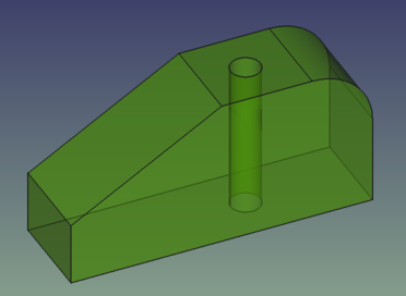
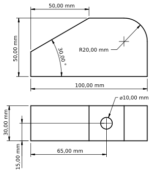
Criando o perfil 2D
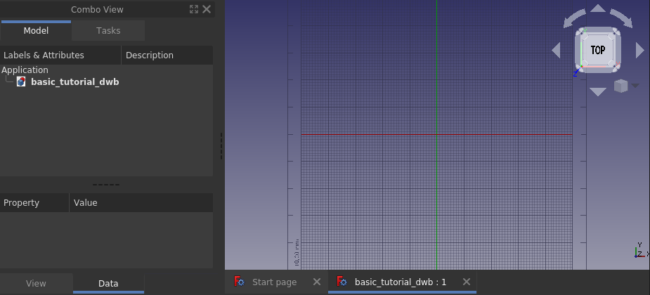
Crie um novo documento e salve-o diretamente com um novo nome. Altere a visualização para Topo e alterne para a visualização
Bancada Draft. Sua tela deve ficar como abaixo. Se a grade não aparecer, ative/desative-a com
Ligar/desligar grade.
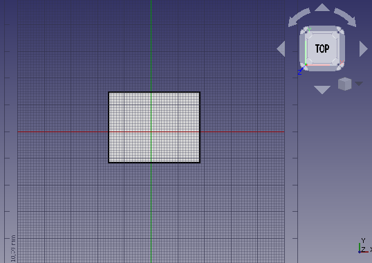
Para iniciar o perfil, desenhe um Retângulo aleatório no plano xy clicando em 2 pontos na Visualização 3D formando qualquer diagonal de um retângulo. Uma aba de Dados se abrirá assim que o retângulo for traçado. Desta vez não vamos usá-la, mas é claro que você pode inserir as coordenadas do retângulo diretamente. Sua visualização 3D agora deve ter um retângulo desenhado, semelhante à imagem abaixo.
Ao trabalhar na bancada Draft quase sempre se desenha em um plano 2D. Esse plano 2D é chamado de Plano de trabalho e, se as configurações padrão forem usadas, ele sempre se alinhará automaticamente à visão 3D atual. Portanto, até que o perfil 2D seja concluído, é melhor simplesmente manter a visualização Topo (posição da câmera) e não brincar com a rotação da visualização. Se por acaso você o alterou, basta voltar para a visualização Topo antes de iniciar qualquer novo comando na bancada Draft.
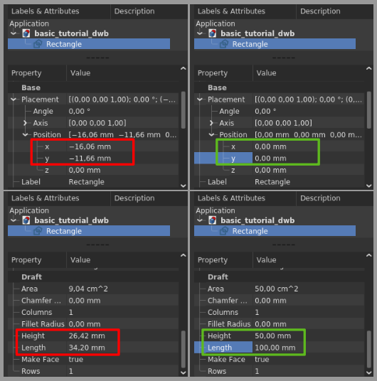
A vista lateral do nosso modelo final tem o contorno externo de 100 x 50 mm, e seria bom se o canto inferior esquerdo fosse colocado na posição zero global. Isso pode ser feito através das Propriedades. Certifique-se de que o objeto Rectangle criado está selecionado na árvore e, em seguida, altere a Posição do retângulo para (0, 0, 0), modifique a Altura (Height) para 50mm e o Comprimento (Lenght) para 100mm conforme as imagens abaixo.
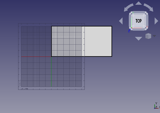
O Rectangle está finalizado e deve ficar assim depois de aplicar Enquadrar tudo na visualização.
Em seguida, vamos dividir o retângulo em suas quatro bordas, isso é feito selecionando primeiro o Rectangle e então o comando Regredir (ou rebaixar), a face preenchida desaparecerá e o objeto na árvore agora é um Wire (arame) ao invés de um Rectangle, mostrado na figura abaixo à esquerda. Usar Regredir mais uma vez quebrará o Wire em suas bordas (edges), mostradas na figura do meio abaixo.

Quem for observador notará que o ícone do objeto na árvore já mudou do Wire para uma caixa azul. Esta caixa azul é o ícone usado para objetos geométricos genéricos (objetos geométricos da bancada Part mais especificamente, mas isso é para leitores avançados). Selecione a borda vertical esquerda e clique em Promover. O objeto Edge agora terá um ícone diferente e mudou o nome para Line. Agora é um objeto da bancada Draft onde se pode editar, por exemplo, o ponto inicial (Start) e o ponto final (End) na aba Propriedades. Isso não é possível com o objetos de borda.
Criando o arredondamento (Filete)
Comece selecionando as laterais superior e direita. Use o menu Editar → Caixa de seleção Seleção de caixa, clique no
botão esquerdo do mouse, arraste da direita pra esquerda, passando a caixa de seleção sobre as laterais e solte-o. Ao arrastar da direita para a esquerda, a seleção resultante inclui tudo total ou parcialmente dentro da área de seleção. Se arrastar da esquerda para a direita, apenas os objetos totalmente incluídos na área de seleção serão incluídos na seleção resultante. A seleção propriamente dita acontece quando o botão esquerdo do mouse é solto, não sendo mostrada previsão do que será selecionado.

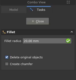
Com as bordas do canto superior direito selecionadas, dê o comando Filete na bancada Draft. Marque Excluir objetos originais, altere o raio para 20mm e pressione enter.
O objeto Fillet é criado e seu modelo agora deve ficar como abaixo.

Criando o chanfro
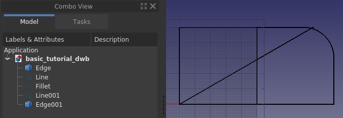
Para fazer o chanfro precisamos ter uma linha com a inclinação correta e também saber posicioná-la corretamente. Comecemos pela posição, que está na coordenada (50, 50, 0). No perfil atual não temos um ponto lá, então vamos criar um fazendo uma linha de ajuda temporária. Primeiro selecione a Linha vertical esquerda, então crie a linha de ajuda com Duplicar seleção em Editar → Duplicar seleção, Line001 é criada. Use as Propriedades e mova Line001 50 mm na direção x usando a propriedade Placement. Em seguida, duplique a borda horizontal inferior, e altere o ângulo da aresta para 30 graus, mais uma vez usando a propriedade Placement. O modelo agora deve se parecer com a imagem abaixo.
Em seguida, mova a linha inclinada para a posição. Para isso, usamos Draft Move juntamente com a funcionalidade snap na bancada Draft, mais especificamente "ponto final" (Adquirir ponto final). Primeiro, certifique-se de que sua barra de ferramentas de encaixe seja semelhante à abaixo.

Em seguida, selecione a linha inclinada, Edge001, pressione Mover e um painel Tarefas se abrirá.
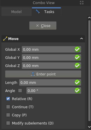
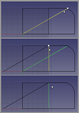
Certifique-se de que Copiar esteja desmarcado. Passe o mouse sobre o quarto superior da linha inclinada, uma vez que o ponto branco é exibido no ponto certo e o símbolo do ponto final aparece, clique no botão 24px esquerdo do mouse. Mova o mouse para o quarto superior da linha auxiliar, assim que o ponto branco e o símbolo do ponto final aparecerem, clique no botão esquerdo do mouse. A sequência é ilustrada abaixo.
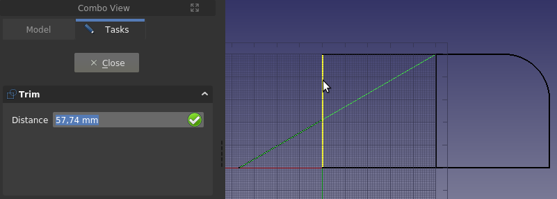
A linha agora está na posição correta, mas é muito longa. Para ajustar o comprimento Trimex será usado. Selecione a linha inclinada, Edge001, pressione Trimex e depois clique na parte inferior da linha vertical mais à esquerda, Line, para usá-la como a aresta de corte. A projeção do ponto onde a aresta de corte é selecionada na aresta a ser cortada, determina o resultado. Se você selecionar a linha vertical mais à esquerda perto de sua extremidade superior, a parte errada da linha angular será aparada. A imagem abaixo mostra o comando Trim, a linha vertical pré-selecionada e o cursor pairando sobre o lado errado dessa linha. Se você olhar com atenção, poderá ver a visualização do resultado.
Apare também a linha vertical mais à esquerda para formar o canto inferior do chanfro. Selecione a linha inclinada, Edge001, perto de seu ponto final superior direito para obter um resultado correto. Se você cometer um erro ao aparar, basta usar Undo e
Refresh (o último geralmente chamado atualizar) e tente novamente.
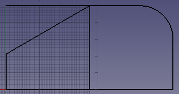
Para aparar a linha superior, o Fillet precisa ser Rebaixado para que a linha superior seja seu próprio objeto na visualização em árvore. Se você tentar apará-lo sem primeiro ter feito o rebaixamento, a função de aparo tentará aparar o arco no filete. Como a borda de corte, a linha vertical do meio, é perpendicular à borda a ser cortada, você não pode controlar o resultado do corte escolhendo um ponto correto na borda de corte. Aqui você precisa inverter a solução padrão mantendo pressionada a tecla Alt enquanto seleciona a aresta de corte.
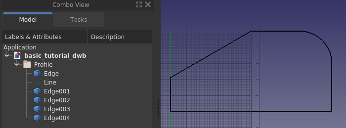
O perfil está pronto e mostrado abaixo com as bordas organizadas em um Grupo chamado Profile (ou rotulado para ser preciso no jargão do FreeCAD), juntamente com a linha de ajuda excluída. Os grupos podem ser usados para organizar os recursos em seus documentos FreeCAD, seu uso é semelhante a uma estrutura de pastas no sistema de arquivos de um computador. Para mover itens para dentro e para fora do grupo, basta arrastar e soltar na árvore.
Why extruding can fail
Save the document. We will experiment in this paragraph and we want to be able to go back to the current model.
Let’s jump right in: select all the edges in the group Profile, and in the Part Workbench invoke the command
Extrude. A task panel opens, accept all the defaults and click OK.

That did not work out, but it sounds easy enough to fix the error, we just need to specify a direction. Click OK to get back to the task panel and select custom direction.
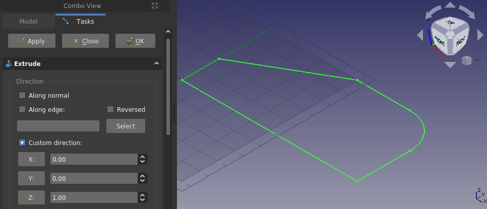
Accept the default z-axis and once more click OK.
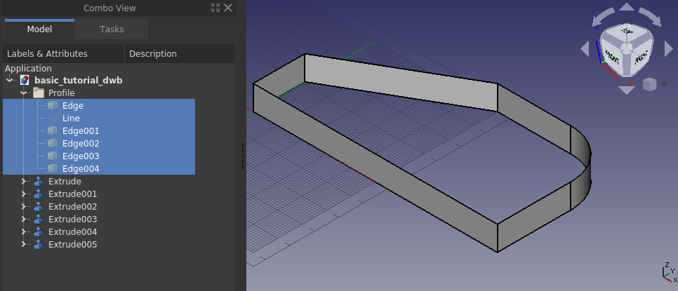
We managed to make a fence like structure, judging from the Tree View every edge is treated separately. It is not the filled solid that we want. Hit Undo, and let’s try something else.
Scrolling all the way to the bottom of the Extrude task panel there is an option Create solid, check that option and click OK.
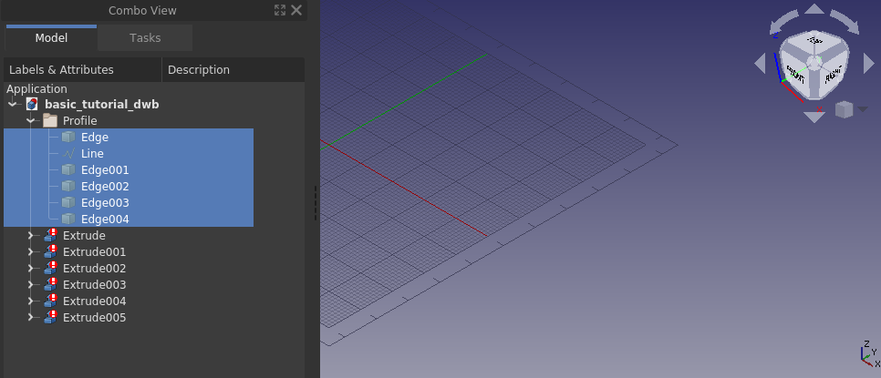
Everything disappeared, clearly that did not work either. Let’s go through why none of these ways are working. In the first case we got an error that the direction could not be determined. A flat face has a normal, i.e. direction, a line does not. Since from our second attempt we know that it worked when providing a direction, the error simply comes from trying to extrude a line without knowing a direction. The observant will say that an arc has a normal (direction), this is true. If you select only the edge that is the arc, FreeCAD will extrude it, also with default settings.
In the second case it worked, but we also got an extrusion for each edge we had in our selection. The resulting features however are not what we want, i.e. a solid.
In the third case we checked Create solid, and ended up with everything disappearing. The objects in the Tree View have a different icon as well, there is a white exclamation mark on a red background, that particular overlay icon means that the object has an error that has to be tended to. One can read up on the different types of overlay icons on the wiki.
Hovering over any of the Tree View objects with the overlay icon a tool tip is displayed, it says Wire is not closed.

In our case the error is not fixable. It is geometrically impossible to create a solid out of an extruded single line. An extruded line simply becomes a sheet, or shell in FreeCAD lingo. In other words, this is not a FreeCAD limitation, it is a fundamental outcome of geometrical theory. The reason why the 3D view goes completely blank is that the created features, or objects in the Tree View, have errors in the produced shape, and thus contain nothing to render. FreeCAD does however create the new document objects (in this case extrusions) and thus hides any geometry/object used for making the new document objects. That is why the screen goes blank when trying to make a solid out of a line, or lines.
The tool tip says it all, in order to extrude into a solid one needs a closed wire, or a face. A face is, per definition, simply a closed wire that is filled. One way to create a closed wire out of our profile edges is to select them all and apply Draft Upgrade. If applied once it becomes a wire, while at the same time it consumes the individual edges from the Tree View. If applied twice it becomes a face, either of those allows for a successful solid extrusion.
Before going on to the next paragraph: open the previous version of the document.
Extruding the profile
Another way to create the closed wire is with the Shape builder command from the Part Workbench, which allows for making a wire without consuming the individual edges. Part Shape builder is a powerful tool to create any geometric entity in FreeCAD that can be used further to create complex solids, the simplest example is creating a line between two vertices. Click Part Shape builder to bring up the task panel.
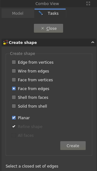
We can use either Wire from edges or Face from edges. Multiple selections have to be made with the Ctrl key pressed down. Let’s use Face from edges, once that option is selected one can also select Planar, do that as well. Then select all edges in the profile, the order does not matter (in this case) and click Create, and then Close to come back to the Tree View. The face has been created.
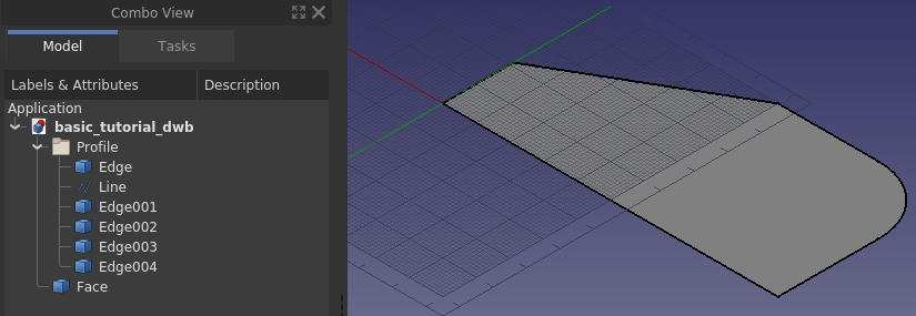
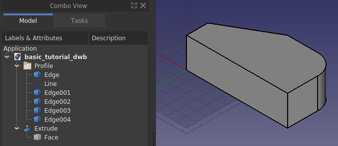
Select the Face and invoke Part Extrude, set the extrusion length to 30 mm and click OK.
Creating the through hole
To make the through hole we need a cylinder correctly positioned to make a boolean cut with.
Create a cylinder, and position it correctly. In this case the radius is 5 mm, the height is set to 60 mm. For the placement, first it is rotated -90 degrees around the x-axis, then positioned at (65, -5, 15). The negative 5 in the y-direction is because the height is 10 mm longer than needed.
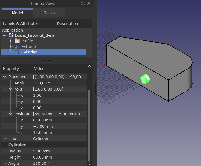
It does not hurt to make the height of the cylinder longer than needed. For a simple model like this it will not matter if the cylinder is the exact height of the profile. It is however good practice to avoid co-planar faces to prevent numerical errors in the geometric kernel that can sometimes result in strange effects, or failures in subsequent operations.
With a final boolean cut, and after changing the appearance of the resulting object, the model is completed.
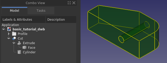
Making a sketch out of the 2D profile
Using the Draft Workbench is one way of creating a 2D profile. In the Draft Workbench a wire can be made in 3D space. FreeCAD provides another tool to make 2D profiles – the Sketcher Workbench. Using a sketch is a more versatile way to create a 2D profile. Any 2D profile made in the Draft Workbench can be converted to an unconstrained sketch.
Start by hiding the Cut feature and make the edges in the profile visible. Select the edges and from the Draft Workbench press the toolbar button Draft to Sketch. You should see the same as in the image below.
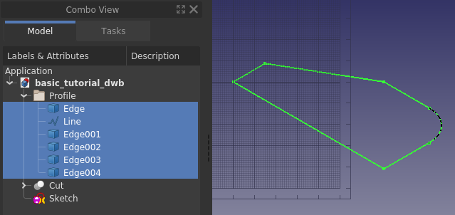
Next, hide the original edges and double-click the Sketch object in the Tree View, bringing you to the following state, i.e. the Sketcher task panel opened.
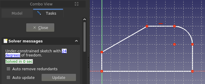
This is how it looks when one edits a sketch. Since this is not a tutorial for using the Sketcher just go ahead and close it. If you want an introduction to sketching, which is a core workflow in any 3D parametric CAD, please follow the sister tutorial Creating a simple part with PartDesign.
With the Sketch closed and selected, from the Part Workbench use Extrude in the same way as before. The basic block of the simple model is ready once again.
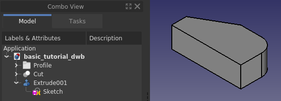
Quality of models
Sooner or later when working with 3D parametric CAD you will come across a broken model, either one you have made yourself, or a model that you have imported. A broken model can work for its purpose, but more often than not, there are subsequent operations that simply will not work. To repair a broken model one has to know what to repair, this is where the built-in quality check tools in FreeCAD come in.
First let us check the quality of the recently created Extrude001. With the Part Workbench active, first select Extrude001 and then use the command Check geometry. Check all settings checkboxes except the top one, and click the Run check button.
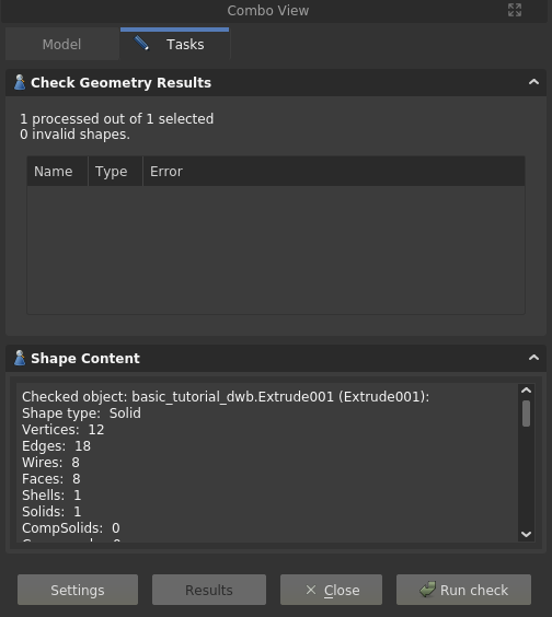
Our model is OK, no errors are reported. There is also a listing of the models content, or in FreeCAD lingo, the content of the shape, i.e. how it is put together from ground up. Here one can see that apparently to make a solid one also needs a shell, and the shell is made out of faces, and so on. In other words, you can create any solid by simply starting out by making points, or vertices, from those one makes edges, and from those one creates wires, and out of the wires one makes faces which are then stitched into a shell, from which one finally arrives at a solid. A solid can only be made from a watertight shell. A not watertight shell is a common source of troublesome CAD models, it can for example happen with imported geometry created in a different software, especially when using the commonly available neutral file formats.
Another check one can do is related to the Sketch. Close the task panel for the geometry check. Select the Sketch, expand Extrude001 in the Tree View if needed in order to see the sketch object. Switch to the Sketcher Workbench, use the command
Validate sketch, a task panel opens. In the task panel, click the Find button for Missing coincidences. It highlights and reports 6 of them, i.e. all the points where the edges meet.
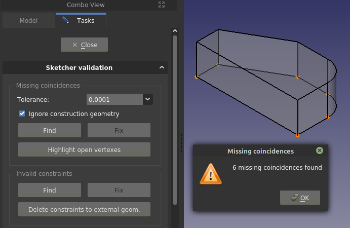
Click OK in the pop-up dialog and then click the Fix button to heal the Missing coincidences. If you close the task panel, and go into edit mode of the Sketch, it reports 12 degrees of freedom, as opposed to the earlier 24. That was achieved through adding coincident constraints to the endpoints of the edges.
The observant reader notices that when using edges from Draft those had to be joined into a closed wire to make a solid extrusion, whereas in Sketcher that was apparently not needed. The logic here is that the sketch is one object, and the extrusion of one object is treated as if it was a closed wire (in this case).
Finally it should be pointed out that, although creating subsequent objects from sketches with open vertices can work, it is best practice to not have any, as well as to have a fully constrained sketch (as opposed to an under-constrained sketch). The reason why it works here is that the sketch is created from a Draft profile constructed in such a way that the endpoints of the edges match without any gaps. If you draw by hand in a sketch, and also try to match endpoints by hand, it is virtually guaranteed that endpoints will not match, i.e. the gaps (although not really visible on the screen) will be large enough that the geometric kernel cannot consider the edges to be geometrically joined.
Wrapping up
Having gone through the tutorial you have become somewhat familiar with the basic functionality of FreeCAD, along with the core workbenches Part and Draft. You are also aware of the existence of the Sketcher Workbench, which for many experienced users is the sole tool used to create 2D profiles later utilized in solid feature operations. The use of sketches is a core concept in the PartDesign Workbench. It is suggested that you learn sketches and PartDesign Workbench next if your focus is on creating solids. The sister-tutorial Creating a simple part with PartDesign makes the same model as this tutorial. If your focus is modeling buildings your next learning should be the Draft and Arch workbenches.
At last, FreeCAD is made by volunteers in their spare time. If you want to further advance FreeCAD’s capabilities, consider contributing to FreeCAD, for example by improving the documentation.