CAM Guida per impazienti
| Topic |
|---|
| Ambiente Path |
| Level |
| Time to complete |
| Authors |
| Chrisb |
| FreeCAD version |
| Example files |
| See also |
| None |
Here is a demonstration showing the creation of a Path WB Job from a 3D Model, generating dialect-correct G-Code for a target CNC mill.
Il modello 3D
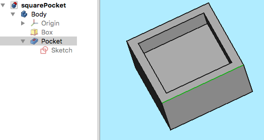
Il progetto inizia con un semplice modello di FreeCAD: un cubo con una tasca rettangolare,
creato nell'ambiente Part Design e formato da un corpo, un cubo con una tasca basata su uno schizzo orientato nel piano XY.
Completato il Modello 3D, selezionare l'ambiente Path.
The Job
The ![]() Job is created.
Job is created.
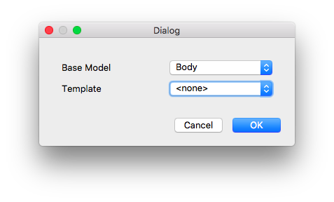
Nella finestra di dialogo Crea lavorazione, fare clic su OK per accettare il Corpo come modello base, senza usare nessun modello.
Impostazione della lavorazione
Nella tabella Azioni si apre la finestra Job Edit e la vista del modello mostra il pezzo grezzo incorniciato dalle linee di un cubo attorno al Corpo base. La scheda selezionata è quella delle Impostazione.
Job Output
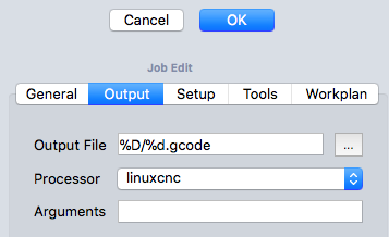
La scheda Output definisce il percorso del file di output, il suo nome e la sua estensione e definisce anche il Postprocessore. Per utenti esperti, è possibile definire gli argomenti dell'algoritmo di post-elaborazione: posizionando il mouse sopra i campi appaiono i suggerimenti per gli argomenti più comuni.
Job Tools
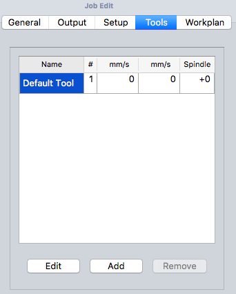
Modifichiamo lo strumento predefinito selezionandolo e facendo clic sul pulsante Modifica. Questo apre la finestra di modifica del Tool Controller.
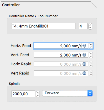
Il nome assegnato all'utensile e il numero dell'utensile corrispondono al numero dell'utensile della macchina. Qui lo strumento è il Nr. 4. Il controller dell'utensile è configurato per avanzamenti orizzontali e verticali di 2mm/s e una velocità del mandrino di 2000 rpm.
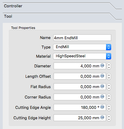
Select the Tool subpanel of the tool controller. Set the diameter and - if you wish to use the simulation tool later - add a cutting edge angle and cutting edge height.
The values are confirmed with OK.
For easy access all the tools can be predefined and selected from the Tool manager.
Job Workplan
The Workplan tab begins empty, and is populated by the sequence of Job Operations, Partial Path Commands, and Path Dressups. The sequence of these items is ordered here.
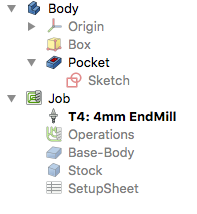
This tree is shown after the Job's configuration once the Path Job is unfolded:
The Path Operations
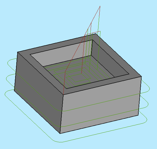
Two operations will be added to generate milling paths for this Path Job. The Contour operation creates a path around the box and the Pocket operation creates a path for the inner pocket.
For now we will keep it simple. The ![]() Contour button opens the Contour panel. After confirming with OK using the default values, see the green path around the object is visible.
Contour button opens the Contour panel. After confirming with OK using the default values, see the green path around the object is visible.
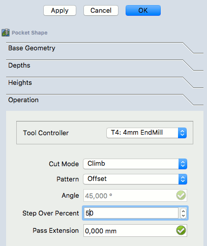
Selecting the bottom of the pocket and then the ![]() Pocket button opens the Pocket Shape window. The default values for Base Geometry, Depths, and Heights are used, and the Operation subpanel is selected, and the Step Over Percent is set at 50.
Pocket button opens the Pocket Shape window. The default values for Base Geometry, Depths, and Heights are used, and the Operation subpanel is selected, and the Step Over Percent is set at 50.
The pattern is changed to "Offset" and the Job Operation is confirmed for the pocket configuration with OK.
The result is a model with two paths:
Verifying Paths
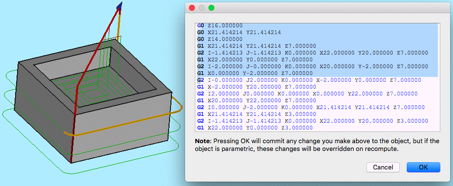
There are two ways to verify the created paths. The G-Code can be inspected, including highlighting the corresponding path segments. The milling process of the Path Job can also be simulated to demonstrate the idealized tool paths, required for the Tool geometries to mill the Stock.
To inspect the G-Code use the ![]() tool. Selecting the corresponding G-Code lines within the G-Code Inspection window highlights individual path segments.
tool. Selecting the corresponding G-Code lines within the G-Code Inspection window highlights individual path segments.
To start the simulation use the ![]() Path Simulator tool.
Path Simulator tool.
Adjust speed and accuracy and start the simulation with the play button.
If you want to end the simulation click the Cancel button, it will remove the stock created for the simulation. If you click Ok this object will be kept in your Job.
Postprocess the Job
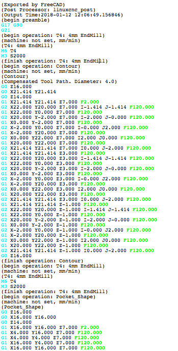
The final step to generate G-Code for the target mill is to postprocess the Job. This outputs the G-Codes to a file that can be uploaded to the target CNC machine controller. To invoke the Postprocessor:
- Select the Job object in the tree
- Select the Path Postprocessing
 tool to postprocess the file. This opens a G-Code window allowing inspection of the final output file before it is saved.
