Thread for Screw Tutorial/fr: Difference between revisions
(Created page with "L'idée est de balayer un profil horizontal le long d'une hélice. Le problème principal est de déterminer quel profil utiliser pour obtenir un filetage.") |
(Created page with "Si on utilise un cercle en guise de profil horizontal (le cercle doit être décentré par rapport à son origine, ce décentrement définissant la profondeur du filetage), le...") |
||
| Line 70: | Line 70: | ||
[[File:thread-by-horz-profile.png|600px]] |
[[File:thread-by-horz-profile.png|600px]] |
||
Si on utilise un cercle en guise de profil horizontal (le cercle doit être décentré par rapport à son origine, ce décentrement définissant la profondeur du filetage), le profil du filetage sera sinusoïdal. |
|||
If one uses a circle as a horizontal profile (the circle has to be placed off the origin, that offset defines the depth of the thread), thread profile will be sinusoidal. |
|||
To obtain a standard sawtooth profile, a pair of mirrored archimedean spirals need to be fused into a wire. The resulting figure is a heart shape, which becomes barely distinguishable from a circle when the depth of the thread is small compared to its diameter (this is why such a "thick" thread is shown on the picture above). |
To obtain a standard sawtooth profile, a pair of mirrored archimedean spirals need to be fused into a wire. The resulting figure is a heart shape, which becomes barely distinguishable from a circle when the depth of the thread is small compared to its diameter (this is why such a "thick" thread is shown on the picture above). |
||
Revision as of 18:03, 31 August 2017
| Thème |
|---|
| Modelsation |
| Niveau |
| Avancé |
| Temps d'exécution estimé |
| Auteurs |
| DeepSOIC, Murdic |
| Version de FreeCAD |
| 0.14 ou plus (dépends de la methode) |
| Fichiers exemples |
| Voir aussi |
| None |
Introduction
Ce tutoriel est un ensemble de techniques pour modéliser un filetage avec FreeCAD.
La modélisation de filets n'est pas recommandée car elle surcharge le noyau de modélisation. Les formes filetées prennent beaucoup de mémoire, et un seul filetage dans un projet FreeCAD peut faire exploser la taille du fichier. Toutefois, il est des situations où il est essentiel de modéliser un filetage dans le détail, et c'est l'objet de ce tutoriel.
Méthode 0. Récupération depuis une bibliothèques d'objets
La réutilisation de modèles créés par d'autres est facile et rapide. Regardez Macro BOLTS, qui est une interface pour l'insertion de pièces standards à partir de la bibliothèque BOLTS.
Méthode 1. Utilisation de macros.
Il y a une fameuse macro Screw Maker, écrite par ulrich1a, et un Atelier Visserie complet écrit par shaise (lien vers GitHub). Ces derniers ont des options pour générer des filets. Ils ciblent les filets de profil standard (triangulaire ou approchant).
Méthode 2. Tricher en empilant des disques.
C'est une très bonne méthode de visualisation des filets, tout en gardant une géométrie simple.
L'idée est de créer un filetage non hélicoïdal (qui est juste une révolution d'un profil en dent de scie, ou un empilement de disques chanfreinés). Un filetage factice de ce type est difficile à distinguer d'un vrai filetage hélicoïdal au premier abord. Cela peut également marcher pour de l'analyse de résistance de matériaux. Par contre, pour de l'impression 3D, cela ne fonctionnera pas.
Méthode 3. Balayage d'un profil vertical.
Idée
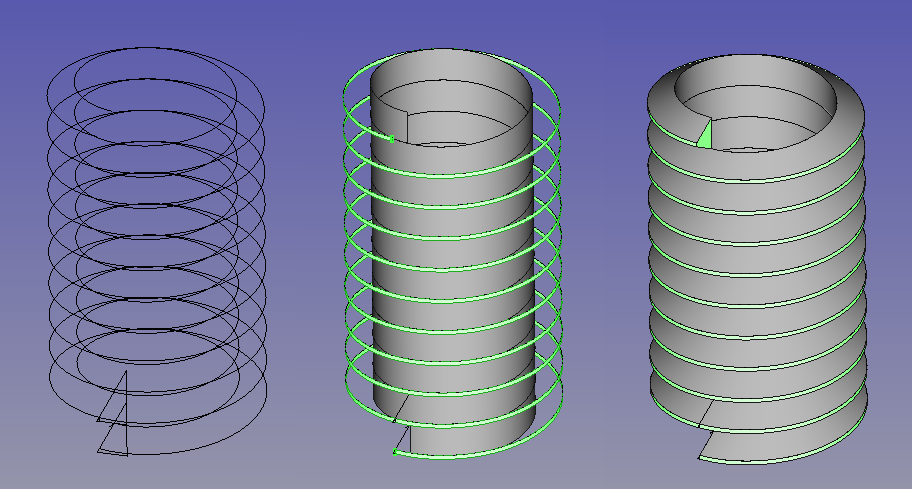
Cette idée est assez simple: dessiner le profil du filetage, et le balayer le long d'une hélice. Lors du balayage, assurez vous de cocher les boites de dialogues Solide et Frenet. Solide est la clé pour permettre de opérations d'union ou de soustraction. Frenet empêchera le profil de se tordre (plus d'info à ce sujet est disponible dans la documentation sur le Balayage).
Cela génère le filet du filetage, sans la barre ou le trou. Pour faire le filetage sur une barre ou dans un trou, il faudra utiliser unir ou soustraire ce filet avec un cylindre. D'autres opérations booléennes seront nécessaire pour façonner le bout du filet laissé brut.
Les clés du succès
Règle 1. le balayage ne doit pas s'intersecter lui même. Un balayage qui s'intersecte n'est pas un solide valide. Les tentatives de fusion ou de soustraction échoueront très certainement. Cependant, pour de l'impression 3D ou des besoins de visualisation, il peut être suffisant de laisser le filet et le cylindre non fusionné (s'intersectant).
Règle 2. Rappelez vous que dans FreeCAD, l'hélice est imprécise. Ainsi, un cylindre créé pour se superposer précieusement avec un filet risquera de ne pas fusionner avec ce dernier. En général, évitez les géométrie coïncidente avec les éléments d'un balayage, comme les face tangentes, les arrêtes tangentes à des faces auxquelles elles ne sont pas connectées, les arrêtes coïncidentes et tangentes, etc...
Astuce 1. Le rayon d'une hélice n'influe pas (à moins que l'hélice ne soit conique). Tout ce qui compte est le pas et la hauteur de l'hélice. Cela implique qu'il est possible d'utiliser une hélice générique pour fabriquer de nombreux filetages de même pas.
Astuce 2. Gardez l'hélice courte (avec peu de tours). Les longs filetages ont tendance à faire échouer les opérations booléennes. Pensez plutôt à empiler des filetages courts pour en faire un long en utilisant Draft Array si vous rencontrez ce genre de situation problématique.
Avantages et inconvénients
+ Une manière très naturelle de faire des filetages
+ Facile à comprendre
+ Pas de problème lors de la génération de mesh contrairement à la méthode 4
- à cause de l'invalidité des balayage qui s'intersectent, il est quasi impossible de générer un filet uniforme (c'est à dire, sans face cylindrique sur les face internes ou externes du filetage).
- Des opérations booléennes sont nécessaires pour avoir des résultats probants. Elles sont longues et échouent souvent.
- Les filetages avec beaucoup de tours sont problématiques
Méthode 4. Balayage d'un profil horizontal
Idée
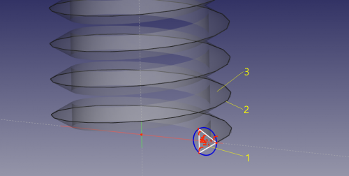
L'idée est de balayer un profil horizontal le long d'une hélice. Le problème principal est de déterminer quel profil utiliser pour obtenir un filetage.
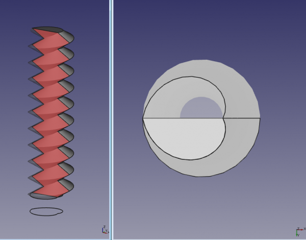
Si on utilise un cercle en guise de profil horizontal (le cercle doit être décentré par rapport à son origine, ce décentrement définissant la profondeur du filetage), le profil du filetage sera sinusoïdal.
To obtain a standard sawtooth profile, a pair of mirrored archimedean spirals need to be fused into a wire. The resulting figure is a heart shape, which becomes barely distinguishable from a circle when the depth of the thread is small compared to its diameter (this is why such a "thick" thread is shown on the picture above).
Generating the profile
Figuring out, what the horizontal profile needs to be made for obtaining a certain vertical profile is not easy. For simple cases like triangular or trapezoidal, it can be constructed manually. Alternatively, it can be constructed by creating a short thread with method 3, and getting a slice of it by doing a common between a horizontal plane face and the thread.
Profile for triangular thread
- Create a spiral (archimedian) in XY plane.
- Set number of turns to 0.5,
- the radius to the inner radius of the thread (outer radius will be this + depth of cut)
- and growth to double the depth of cut of the thread.
- Part Mirror the spiral against XY plane
- Part Union the spiral and the mirror to obtain a closed wire, shaped like a heart. Done!
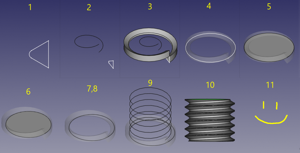
Profile for arbitrary cross-section
- make a (vertical) cut profile. Make sure that the height of the sketch matches the pitch of the thread you need.
- make a helix1 with height identical to the pitch and the pitch identical to the thread pitch and a helix radius of 0.42*nominal diameter of the thread.
- Sweep the cut profile along the helix1. Set make solid and frenet to true.
- Make a circle with nominal radius of the thread in the x-y-plane.
- Make a face from the circle. (Part-workbench: advanced utility to create shapes, or Draft Upgrade then MakeFace = true)
- cut the face with the sweep profile
- make a clone from the cut (Draft workbench)
- Downgrade the clone in order to get a wire. (Draft workbench) This wire is the horizontal profile needed for this method.
- Make a helix with radius of nominal radius of the thread and a pitch of the thread and the height of the needed thread.
- Sweep the wire along the helix. Set solid and frenet to true.
You are done.
Credit: step-by-step guide from a forum post by Ulrich1a, slightly modified.
The steps are also shown in action on this video by Gaurav Prabhudesai: http://www.youtube.com/watch?v=fxKxSOGbDYs
Pros and cons
+ A ready-to-use thread-on-a-rod solid shape is created by the sweep directly.
+ Less or even no Boolean operations required, generation speed is very high compared to Method 3.
+ Thread ends are nicely cut straight away
+ Long threads are not a problem, unless a Boolean operation is needed. Otherwise, it is not going to be much better than Method 3.
+ Gapless threads are not a problem.
- Defining thread profile is complicated.
- Standard mesher generates ugly meshes, which can lead to problems. Other meshers are better, Mefisto seems to give the best results.
- large memory footprint [1]
Method 5. Lofting between helical extruded faces
Idea
Helical splines will extrude coaxial faces that are able to be lofted, while FreeCAD's parametric helix won't. It takes two helical splines to define a thread. Those two can be scaled from a library spline, then located and extruded appropriately to get the form right.
FreeCAD's parametric helixes aren't truly helical, but helical b-splines aren't difficult to lay out. One manual method is to array dodecagons (12-sided polygons) with 5mm radius/10mm diameter at 1/12mm (0.08333.mm) z intervals and trace splines from vertex to vertex in ascending and rotating order, and to consider doing it once with, say, 10 turns, so that that spline can be re-used as a library file for import and reuse. It's convenient to use 10mm diameter/1mm pitch for ease of scaling. If you are doing it manually, drawing a Dwire and then converting it to a b-spline is easier than drawing a spline. Dwires don't have curvature computed while being drawn, so they follow the cursor and snap more obediently.
Once the splines are scaled to the right size and located so that the loft will have the right included angle between the thread flanks, they're extruded along their axis, a pitch length's worth for the inner spline, the outer pitch/8.
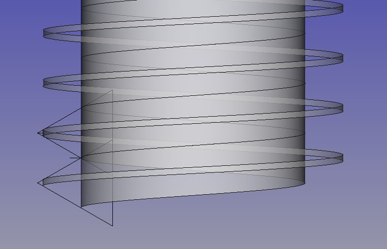
ISO and other threads have relieved, ie flat, inner and outer edges rather than sharp, which suits FreeCAD users with this method, because we can loft to the helical face at the nominal fastener size, while an inner face can't be lofted to an outer edge spline because a face is a closed profile, a spline is open. ISO standard says the nominal size of external threads have a face width pitch/8. The picture shows how the geometry is arranged, and the helical faces that result. Then, loft between the faces, and then a cylinder that gives the inner helical face, which ISO puts at pitch/4 width, is added to the threads.
This method produces reliable solids that boolean properly. While it doesn't produce "parametric" screw threads in standard sizes in the sense of having simple access to form by fastener size, it's an easy way of producing an accurate library for reuse, and models of specialised forms like ACME, or Archimedian screws, are also uncomplicated as one-offs.


