Part Ausformung
|
|
| Menüeintrag |
|---|
| Part → Loft... |
| Arbeitsbereich |
| Part |
| Standardtastenkürzel |
| Keiner |
| Eingeführt in Version |
| - |
| Siehe auch |
| Part Sweep |
Überblick
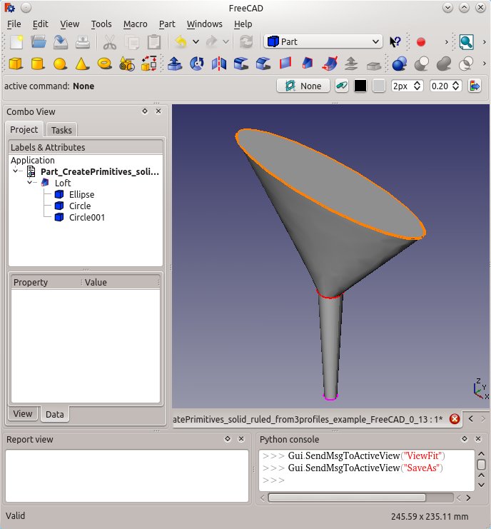
Das FreeCAD-Loft-Werkzeug (Arbeitsbereich Part) wird verwendet um eine Fläche, eine Hülle oder einen Körper aus zwei oder mehr Konturen (Profilen) zu erstellen. Die Konturen können entweder ein Punkt (vertex), eine Kante (Edge), Linienzug (wire) oder eine Fläche (face) sein. Kanten und Linienzüge können entweder offen oder geschlossen sein. Es gibt zahlreiche Einschränkungen und Implikationen, siehe unten. Als Konturen können die Primitive des Arbeitsbereichs Part, Zeichnungen aus dem Arbeitsbereich Entwurf (Draft) und Skizzen des Sketchers verwendet werden.
Das Loft-Werkzeug hat drei Parameter, "Regelfläche","Erzeuge Volumenkörper" und "Geschlossen" die alle den Status wahr oder falsch annehmen können.
Wenn "Regelfläche" "wahr" ist, erzeugt FreeCAD eine Fläche, eine Hülle oder einen Körper mit Regelflächen. Regelfläche auf Wikipedia.
Wenn "Erzeuge Volumenkörper" "wahr" ist, erzeugt FreeCAD einen Körper, falls die Konturen geschlossen sind. Im Falle von "falsch" erzeugt FreeCAD eine Fläche oder eine Hülle bei mehreren Kanten sowohl für offene oder geschlossene Konturen.
Wenn "Geschlossen" "wahr" ist, versucht FreeCAD das erste mit dem letzten Profil durch eine geschlossene Geometrie zu verbinden.
For more info on how the profiles are joined together, refer Part Loft Technical Details page.

Limitations and complications
- A vertex or point
- vertex or point may only be used as the first and/or last profile in the list of profiles.
- For example
- you can not loft from a circle to a point, to a ellipse.
- However you could Loft from a point to a circle to an ellipse to another point.
- For example
- vertex or point may only be used as the first and/or last profile in the list of profiles.
- Open or closed geometry profiles can not be mixed in one single Loft
- In one Loft, all profiles (lines wires etc.) must be either open or closed.
- For example
- FreeCAD can not Loft between one Part Circle and one default Part Line.
- For example
- In one Loft, all profiles (lines wires etc.) must be either open or closed.
- Draft Workbench features
- Draft Workbench features can be directly used as a profile in FreeCAD 0.14 or later.
- For example the following Draft features can be used as profiles in a Part Loft
- Draft Polygon.
- Draft Point, Line, wire,
- Draft B-spline, Bezier Curve
- Draft Circle, Ellipse, Rectangle
- For example the following Draft features can be used as profiles in a Part Loft
- Draft Workbench features can be directly used as a profile in FreeCAD 0.14 or later.
- PartDesign Sketches
- The profile may be created with a sketch. However only a valid sketch will be shown in the list to be available for selection.
- The sketch must contain only one open or closed wire or line (can be multiple lines, if those lines are all connected as they are then a single wire)
- Part Workbench
- the profile can be a valid Part geometric primitive which can be created with the Part CreatePrimitives tool
- For example the following Part geometric primitives can be a valid profile
- Point (Vertex), Line (Edge)
- Helix, Spiral
- Circle, Ellipse
- Regular Polygon
- Plane (Face)
- For example the following Part geometric primitives can be a valid profile
- the profile can be a valid Part geometric primitive which can be created with the Part CreatePrimitives tool
- Closed Lofts
- The results of closed lofts may be unexpected - the loft may develop twists or kinks. Lofting is very sensitive to the Placement of the profiles and the complexity of the curves required to connect the corresponding Vertices in all the profiles.
An example Loft
The Loft tool is in the Part Workbench, menu Part -> Loft... or via the icon in the tool bar.
In the "Tasks" will be two lists: "node / wire" and "free form".
Selection of the elements
In the "node / wire" the available items are displayed. Two elements must be selected one after the first in this list.
Thereafter, with the blue arrow that item is added to the list of "free form".
The selected items must be of the same type.
Tip: the active / selected items in the list are displayed in the 3D area as active / selected.
Command complete
If both elements are selected, the command can be completed with "OK".
Result
From closed lines we get surfaces which might be taken as a superficial look for solids.
If indeed a solid needs to be created, used the button "Create Solid" or after creating the Loft switch to its properties tab data and set the switch "Solid" to true.
The procedure is the same as described above with open polylines.
FreeCAD Version
- added Version 0.13
- "closed" property added Version 0.14
- Ability to use a face as a profile added Version 0.14


