PartDesign Tutorium
| Thema |
|---|
| Skizzieren |
| Niveau |
| Anfänger |
| Zeit zum Abschluss |
| 15 Minuten |
| Autoren |
| Drei |
| FreeCAD-Version |
| 0.16 oder neuer |
| Beispieldateien |
| Siehe auch |
| None |
Einleitung
Dieses Tutorial soll den Leser in die Grundlagen des Arbeitsbereichs PartDesign einführen. Es wird gezeigt, wie 3D-Objekte erstellt werden, die auf Skizzen basieren, Subtraktions-Operationen durchgeführt und wie bestimmte Merkmale in einer Anordnung (pattern) repliziert werden.
Voraussetzungen
- FreeCAD Version 0.16 oder neuer
- Das Leser hat das Sketcher Tutorial bereits absolviert
Vorgehensweise
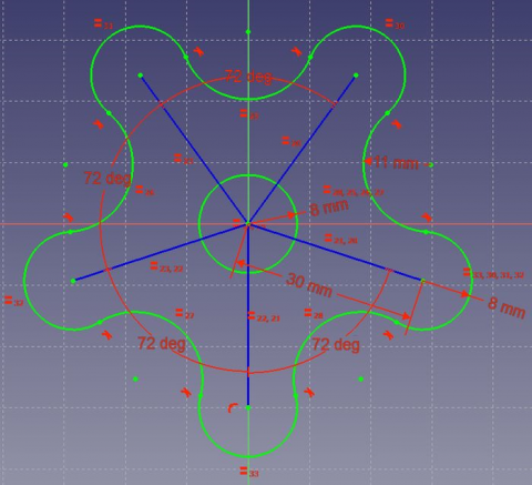
Erstellen von 3D-Geometrie
Der Zweck des Arbeitsbereichs PartDesign ist es, dreidimensionale Objekte für einen bestimmten Bedarf zu erstellen. Zu diesem Zweck ist der Arbeitsbereich mit Werkzeugen ausgestattet, mit denen 2D-Skizzen in 3D-Objekte konvertiert werden können.
Es gibt zwei grundlegende Funktionen, um dies zu erreichen: Block ![]() und Rotation
und Rotation ![]() . Daneben gibt es noch deren negative Pendants (Tasche
. Daneben gibt es noch deren negative Pendants (Tasche ![]() und Nut
und Nut ![]() ). Zusammen stellen diese vier Funktionen die wichtigsten Werkzeuge dieses Arbeitsbereichs dar.
). Zusammen stellen diese vier Funktionen die wichtigsten Werkzeuge dieses Arbeitsbereichs dar.
- Wechseln Sie in den Arbeitsbereich PartDesign.
- Wählen Sie die im Sketcher Tutorial erstellte Skizze aus.
- Klicken Sie auf die Schaltfläche Block
 .
. - Geben Sie als Länge 5 mm ein.
- Klicken Sie auf OK.
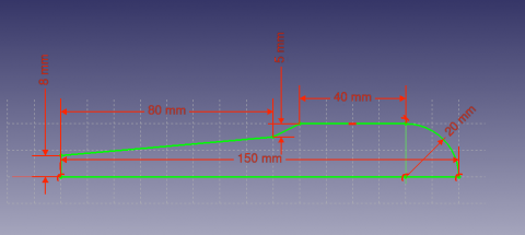
Eine andere Möglichkeit zum Erzeugen von 3D-Geometrie ist das Werkzeug Rotation ![]() .
.
- Erstellen Sie eine Skizze basierend auf dem oben gezeigten Bild.
- Klicken Sie auf Rotation
 .
. - Geben Sie beim Winkel 360° ein.
Subtracting Features
We'll begin by creating a sketch with the shape we want to subtract.
- Select the top flat face of the "Revolution"
- Select
 New sketch
 - Select
 External Geometry
 - Approach the edge of the pad. An arc should be highlighted
- Select the arc. An arc of a different color should appear in the sketch
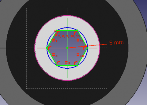
- Create a hexagon centered on the same point as the arc and set the radius of the reference circle to 5 mm
When a 3D element has been created it is possible to create references to it within a sketch.
- Select
 External Geometry.
 - Approach the element that you wish to reference, the edge of a Pad for example.
- Click on it
- New elements of a different color should appear on the sketch in the location of the feature you wish to reference.
Afterwards, we'll proceed to apply a Pocket feature.
- Select the sketch
- Select
 Pocket
 - Set the distance to Through all
Pattern Features
Recall the extruded profile that was created at the start of the tutorial.
- Select the top face of the object
- Create a new Sketch
- Create reference geometry linked to the top arm of the figure
- Create a circle constrained to the center of the reference arc
- Set its radius to 3 mm
- Pocket the sketch through all the workpiece
Instead of creating a circle for each hole in the sketch, we will introduce the concept of Pattern Features. These tools operate by replicating a feature in the workpiece that has already been created and that we wish to reproduce in a linear or circular arrangement. We will use a combination of Linear and Polar pattern features simulatneously to obtain the final workpiece.
- Select the Pockt feature that we just created in the Tree View
- Select
 MultiTransform
In the Combo View we are now asked to introduce the Transformations that we desire. Notice that in the MultiTransform parameters menu we see that FreeCAD has identified the Pocket as the Original feature and a second box requests us to Right click it to introduce the pattern features.
- Right click the box
- Select Add Linear Pattern
- Set the Direction to Vertical Sketch Axis
- Set length to 10 mm
- Leave occurrences at 2
- Click OK
- Right click the box again to add a Polar Pattern. Notice that the 3D view has now added the linear pattern.
- Set occurrences to 5
- Click OK twice
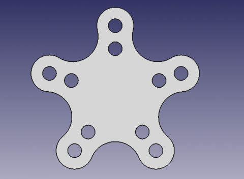
After completing this task you should have the following result.
If not, re-edit the MultiTransform operation by double clicking on it in the Tree View. Check both pattern features to detect necessary modifications, such as the Axis and if the Direction needs to be reversed.
We are now finished with the basic workflow for the PartDesign Workbench.


