PartDesign WizardShaft/ja: Difference between revisions
(Created page with "{{GuiCommand/jp|Name=PartDesign_WizardShaft|Workbenches=パートデザイン, Complete}}") |
(Updating to match new version of source page) |
||
| (23 intermediate revisions by 3 users not shown) | |||
| Line 1: | Line 1: | ||
<languages/> |
<languages/> |
||
{{GuiCommand/jp|Name=PartDesign_WizardShaft|Workbenches=[[PartDesign Workbench/jp|パートデザイン]], Complete}} |
|||
{{Docnav |
|||
==Introduction== |
|||
|[[PartDesign_InvoluteGear|Involute gear]] |
|||
This tool allows you to create a shaft from a table of values, and to analyse forces and moments. You can start the wizard from the Part Design menu or by typing |
|||
|[[PartDesign_MoveTip|Set tip]] |
|||
|[[PartDesign_Workbench|PartDesign]] |
|||
|IconL=PartDesign_InternalExternalGear.svg |
|||
|IconR=PartDesign_MoveTip.svg |
|||
|IconC=Workbench_PartDesign.svg |
|||
}} |
|||
<div class="mw-translate-fuzzy"> |
|||
{{Code|code= |
|||
{{GuiCommand/ja |
|||
Gui.runCommand('PartDesign_WizardShaft') |
|||
|Name=PartDesign_WizardShaft |
|||
|Name/ja=PartDesign_WizardShaft |
|||
|Workbenches=[[PartDesign Workbench/ja|パートデザイン]], Complete |
|||
}} |
}} |
||
</div> |
|||
==Description== |
|||
into the Python console of FreeCAD. The wizard will start and show a default table, the corresponding shaft part and force/moment graphs. |
|||
<div class="mw-translate-fuzzy"> |
|||
[[Image:WizardShaft_Part.jpg|780px]] |
|||
==イントロダクション== |
|||
このツールを使うと値のテーブルからシャフトを作成し、その力とモーメントを解析することができます。 |
|||
</div> |
|||
==Usage== |
|||
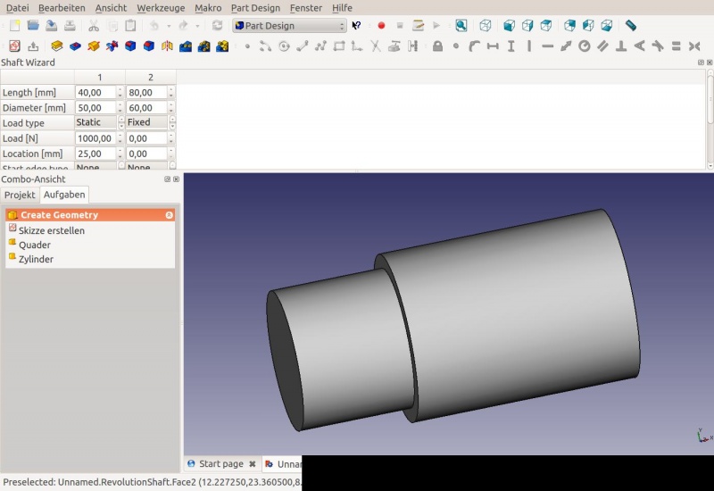
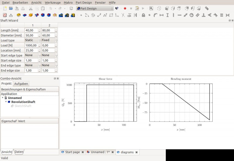
The top of the window is taken up by the table. It is organized into numbered columns which correspond to segments of the shaft. A shaft segment is characterized by having certain length and diameter. The main window shows two tabs. One is the shaft part itself (a revolution feature), shown in the image above. The second tab shows graphs of the shear forces and moments created by the loads defined in the table. |
|||
You can start the wizard from the Part Design menu {{MenuCommand|Part Design → [[File:PartDesign_WizardShaft.svg|20px]] Shaft design wizard...}}. |
|||
[[Image:shaftwizard1.jpg|1024px]] |
|||
<div class="mw-translate-fuzzy"> |
|||
FreeCADのPythonコンソールに |
|||
Gui.runCommand('PartDesign_WizardShaft') |
|||
と入力するとウィザイードが起動します。ウィザードは起動するとデフォルトのテーブル、対応するシャフト部品、力/モーメントのグラフを表示します。 |
|||
</div> |
|||
<div class="mw-translate-fuzzy"> |
|||
[[Image:WizardShaft_Part.jpg|800px]] |
|||
</div> |
|||
ウィンドウの上部にはテーブルが表示されます。テーブルはシャフトの区分と対応する数値の振られた列で構成されます。シャフトの区分は長さと直径によって特徴づけられています。メインウィンドウには二つのタブが表示されます。一つにはシャフト部品そのもの(回転形状)が上記の画像のように表示されます。もう一つのタブにはテーブルで定義された負荷に対するせん断応力とモーメントのグラフが表示されます。 |
|||
<div class="mw-translate-fuzzy"> |
|||
[[Image:shaftwizard1.jpg|800px]] |
|||
{{clear}} |
{{clear}} |
||
---- |
|||
</div> |
|||
==Prerequisites== |
==Prerequisites== |
||
The shaft design wizard depends on the [http://matplotlib.org/ matplotlib] library to create and display the graphs of shear force and bending moment. On Debian/Ubuntu-based systems, it is available through the python-matplotlib package. |
|||
<div class="mw-translate-fuzzy"> |
|||
==必須== |
|||
シャフト設計ウィザードはせん断応力と曲げモーメントのグラフを作成、表示するためにnumpyパッケージとpyxplotプログラムを使用しています。 |
|||
==パラメーター== |
|||
シャフトの各区分には以下のパラメーターが定義可能です。 |
|||
* 区分の長さ |
|||
* 区分の直径 |
|||
* 負荷のタイプ。メニューをスクロールして適切な項目ををクリックする必要があることに注意してください。そうしないと選択されません! |
|||
** None: 負荷なし |
|||
** Fixed: シャフトの末端を固定(例えば他の部品に溶接されている場合)。この負荷タイプは最初の区分、または最後の区分にのみ定義できます。 |
|||
** Static: シャフト区分に静荷重あり |
|||
* シャフトの区分にかける負荷 |
|||
* 区分の中で負荷がかける位置。位置は区分左端からの距離で定義されます。 |
|||
(この他にも行、負荷タイプがありますがまだ機能が実装されていません) |
|||
</div> |
|||
==Parameters== |
==Parameters== |
||
For each shaft segment, the following parameters can be defined |
For each shaft segment, the following parameters can be defined |
||
* Length of the segment |
* Length of the segment |
||
| Line 33: | Line 79: | ||
==Menus== |
==Menus== |
||
To add a new shaft segment, right-click into the empty space to the right of the table, and choose "Add column". |
|||
<div class="mw-translate-fuzzy"> |
|||
==メニュー== |
|||
新しいシャフトの区分を追加するにはテーブルの右側の何もない領域で右クリックして"Add column"を選択します。 |
|||
</div> |
|||
==Limitations== |
==Limitations== |
||
* It is not possible to have adjacent shaft segments with the same diameter. |
|||
<div class="mw-translate-fuzzy"> |
|||
==制限事項== |
|||
* 同じ直径のシャフト区分を隣接して配置することはできません。 |
|||
</div> |
|||
==Planned functionality== |
==Planned functionality== |
||
* Table-driven chamfers and rounds on the shaft edges |
|||
<div class="mw-translate-fuzzy"> |
|||
* Recognize a previously created shaft wizard part and initialize the table values from it |
|||
==計画中の機能== |
|||
* Shaft stress calculation |
|||
* テーブルによるシャフトの辺の面取りと丸め込み |
|||
* Visualization of loads on the shaft (can use the same functionality as for FEM module) |
|||
* 以前に作成したシャフトウィザード部品の認識とそれによるテーブル値の初期化 |
|||
* Definition of loads as a Document Object (can use the same functionality as for FEM module) |
|||
* シャフトの圧力計算 |
|||
* Material database |
|||
* シャフトにかかる負荷の可視化(FEMモジュールと同じ機能が使用可能) |
|||
* Allow loads in the Z-direction as well as in Y-direction (requires definition of loads as a Document Object, otherwise the table will become very long) |
|||
* ドキュメントオブジェクトとして負荷を定義(FEMモジュールと同じ機能が使用可能) |
|||
* 物性データベース |
|||
* Y方向と同様にZ方向への負荷を許可(負荷をドキュメントオブジェクトとして定義する必要があります。そうしないとテーブルが非常に長くなってしまいます) |
|||
{{clear}} |
|||
</div> |
|||
{{Docnav |
|||
|[[PartDesign_InvoluteGear|Involute gear]] |
|||
|[[PartDesign_MoveTip|Set tip]] |
|||
|[[PartDesign_Workbench|PartDesign]] |
|||
|IconL=PartDesign_InternalExternalGear.svg |
|||
|IconR=PartDesign_MoveTip.svg |
|||
|IconC=Workbench_PartDesign.svg |
|||
}} |
|||
{{PartDesign Tools navi{{#translation:}}}} |
|||
{{Userdocnavi{{#translation:}}}} |
|||
Latest revision as of 15:29, 2 June 2023
|
|
| メニューの場所 |
|---|
| None |
| ワークベンチ |
| パートデザイン, Complete |
| デフォルトのショートカット |
| None |
| バージョンで導入 |
| - |
| も参照してください |
| None |
Description
イントロダクション
このツールを使うと値のテーブルからシャフトを作成し、その力とモーメントを解析することができます。
Usage
You can start the wizard from the Part Design menu Part Design → Shaft design wizard....
FreeCADのPythonコンソールに
Gui.runCommand('PartDesign_WizardShaft')
と入力するとウィザイードが起動します。ウィザードは起動するとデフォルトのテーブル、対応するシャフト部品、力/モーメントのグラフを表示します。
ウィンドウの上部にはテーブルが表示されます。テーブルはシャフトの区分と対応する数値の振られた列で構成されます。シャフトの区分は長さと直径によって特徴づけられています。メインウィンドウには二つのタブが表示されます。一つにはシャフト部品そのもの(回転形状)が上記の画像のように表示されます。もう一つのタブにはテーブルで定義された負荷に対するせん断応力とモーメントのグラフが表示されます。
Prerequisites
必須
シャフト設計ウィザードはせん断応力と曲げモーメントのグラフを作成、表示するためにnumpyパッケージとpyxplotプログラムを使用しています。
パラメーター
シャフトの各区分には以下のパラメーターが定義可能です。
- 区分の長さ
- 区分の直径
- 負荷のタイプ。メニューをスクロールして適切な項目ををクリックする必要があることに注意してください。そうしないと選択されません!
- None: 負荷なし
- Fixed: シャフトの末端を固定(例えば他の部品に溶接されている場合)。この負荷タイプは最初の区分、または最後の区分にのみ定義できます。
- Static: シャフト区分に静荷重あり
- シャフトの区分にかける負荷
- 区分の中で負荷がかける位置。位置は区分左端からの距離で定義されます。
(この他にも行、負荷タイプがありますがまだ機能が実装されていません)
Parameters
For each shaft segment, the following parameters can be defined
- Length of the segment
- Diameter of the segment
- Load type. Note that you have to click on the desired entry in the menu after scrolling to it, otherwise it will not be selected!
- None: No load
- Fixed: The end of the shaft is fixed (e.g. welded to another part). This load type can only be defined for the first or last segment.
- Static: There is a static load on this shaft segment
- Load on the shaft segment
- Location where the load is applied to the segment. The location is counted from the left-hand edge of the segment
(Other rows and load types exist but no functionality has been implemented yet)
Menus
メニュー
新しいシャフトの区分を追加するにはテーブルの右側の何もない領域で右クリックして"Add column"を選択します。
Limitations
制限事項
- 同じ直径のシャフト区分を隣接して配置することはできません。
Planned functionality
計画中の機能
- テーブルによるシャフトの辺の面取りと丸め込み
- 以前に作成したシャフトウィザード部品の認識とそれによるテーブル値の初期化
- シャフトの圧力計算
- シャフトにかかる負荷の可視化(FEMモジュールと同じ機能が使用可能)
- ドキュメントオブジェクトとして負荷を定義(FEMモジュールと同じ機能が使用可能)
- 物性データベース
- Y方向と同様にZ方向への負荷を許可(負荷をドキュメントオブジェクトとして定義する必要があります。そうしないとテーブルが非常に長くなってしまいます)
- Structure tools: Part, Group
- Helper tools: Create body, Create sketch, Edit sketch, Map sketch to face
- Modeling tools
- Datum tools: Create a datum point, Create a datum line, Create a datum plane, Create a local coordinate system, Create a shape binder, Create a sub-object(s) shape binder, Create a clone
- Additive tools: Pad, Revolution, Additive loft, Additive pipe, Additive helix, Additive box, Additive cylinder, Additive sphere, Additive cone, Additive ellipsoid, Additive torus, Additive prism, Additive wedge
- Subtractive tools: Pocket, Hole, Groove, Subtractive loft, Subtractive pipe, Subtractive helix, Subtractive box, Subtractive cylinder, Subtractive sphere, Subtractive cone, Subtractive ellipsoid, Subtractive torus, Subtractive prism, Subtractive wedge
- Transformation tools: Mirrored, Linear Pattern, Polar Pattern, Create MultiTransform, Scaled
- Dress-up tools: Fillet, Chamfer, Draft, Thickness
- Boolean: Boolean operation
- Extras: Migrate, Sprocket, Involute gear, Shaft design wizard
- Context menu: Set tip, Move object to other body, Move object after other object, Appearance, Color per face
- Getting started
- Installation: Download, Windows, Linux, Mac, Additional components, Docker, AppImage, Ubuntu Snap
- Basics: About FreeCAD, Interface, Mouse navigation, Selection methods, Object name, Preferences, Workbenches, Document structure, Properties, Help FreeCAD, Donate
- Help: Tutorials, Video tutorials
- Workbenches: Std Base, Arch, Assembly, CAM, Draft, FEM, Inspection, Mesh, OpenSCAD, Part, PartDesign, Points, Reverse Engineering, Robot, Sketcher, Spreadsheet, Surface, TechDraw, Test Framework
- Hubs: User hub, Power users hub, Developer hub

