PartDesign Verrundung
|
|
| Menüeintrag |
|---|
| PartDesign → Verrundung |
| Arbeitsbereich |
| PartDesign, Complete |
| Standardtastenkürzel |
| Keiner |
| Eingeführt in Version |
| - |
| Siehe auch |
| Part Fillet |
Beschreibung
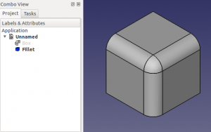
Dieses Werkzeug erstellt Verrundungen an den ausgewählten Kanten eines Objekts. Ein neues separates Fillet-Formelement (benannt mit Fillet und einer fortlaufenden Nummer, wenn im Dokument bereits Verrundungen vorhanden sind) wird im Modellbaum erstellt.


Anwendung
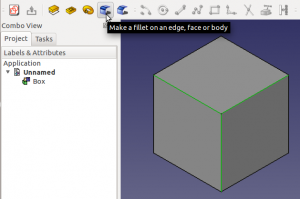
- Wähle eine einzelne oder mehrere Kanten an einem Objekt aus und starte das Werkzeug, in dem Du entweder auf den
 PartDesign Chamfer-Button klickst oder PartDesign → Chamfer aus der Menüleiste aufrufst.
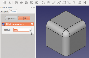
 - Lege in den Rundungs-Parametern im Aufgaben-Panel den Radius durch Werteingabe oder Klick auf die Auf- / Ab-Pfeile fest. Die angewendete Verrundung wird in Echtzeit angezeigt.
- Klicke OK, um zu bestätigen.
- Für eine Kette von tangentialen Kanten kann eine einzelne Kante ausgewählt werden; Die Verrundung breitet sich entlang der Kette aus.
- Um die Verrundung nach der Validierung der Funktion zu bearbeiten, doppelklicke entweder auf die Verrundung-Beschriftung in der Projektnavigation oder klicke mit der rechten Maustaste darauf und wählen Verrundung bearbeiten.
PartDesign Fillet VS. Part Fillet
The PartDesign Fillet is not to be confused with its Part workbench counterpart. Although they share the same icon, they are not the same, and are not used the same way. Here is how they differ from each other:
- The PartDesign Fillet is parametric. After a fillet has been applied, its radius can be edited; this is not possible with the Part Fillet.
- Edges must be selected on an object before activating the PartDesign Fillet. WIth the Part Fillet, the tool can be started, then a solid is selected, then edges.
- The PartDesign Fillet creates a separate Fillet entry (followed by a sequential number if there are already existing fillets) in the Project tree. The Part Fillet becomes the parent of the object it was applied to.
- The PartDesign Fillet offers a live preview of the fillet applied to the object before validating the function.
- The Part Fillet supports variable radii (with a start radius and an end radius). The PartDesign fillet doesn't.
Known Issues
Fillets, chamfers, and other features that operate on solid bodies depend on the underlying OCC kernel that FreeCAD uses. The OCC kernel occasionally has difficulty handling coincident sharp edges, where two faces meet. If this is the case FreeCAD may crash without an explanation.
If run from the terminal, FreeCAD may output a log like this one after the crash:
#1  0x7fff63d660ba in BRep_Tool::Curve(TopoDS_Edge const&, TopLoc_Location&, double&, double&) from /usr/lib/x86_64-linux-gnu/libTKBRep.so.7+0x2a
#2  0x7fff63d69546 in BRep_Tool::Curve(TopoDS_Edge const&, double&, double&) from /usr/lib/x86_64-linux-gnu/libTKBRep.so.7+0x46
#3  0x7fff71f4fef5 in ChFi3d_Builder::PerformIntersectionAtEnd(int) from /usr/lib/x86_64-linux-gnu/libTKFillet.so.7+0x3b05
#4  0x7fff71f58307 in ChFi3d_Builder::PerformOneCorner(int, bool) from /usr/lib/x86_64-linux-gnu/libTKFillet.so.7+0x1097
#5  0x7fff71ef6218 in ChFi3d_Builder::PerformFilletOnVertex(int) from /usr/lib/x86_64-linux-gnu/libTKFillet.so.7+0x4e8
#6  0x7fff71ef71d1 in ChFi3d_Builder::Compute() from /usr/lib/x86_64-linux-gnu/libTKFillet.so.7+0xe31
#7  0x7fff720ad7c3 in BRepFilletAPI_MakeChamfer::Build() from /usr/lib/x86_64-linux-gnu/libTKFillet.so.7+0x33
#8  0x7fff723be48e in PartDesign::Chamfer::execute() from /usr/lib/freecad-daily/lib/_PartDesign.so+0x60e
...
This output references functions located in libTKBRep.so, libTKFillet.so, etc., which are OCC libraries. If these type of crashes occur, the problem may need to be reported and solved in OCC rather than in FreeCAD.
See the forum threads for more information:
The user is also responsible for the integrity of his or her own model. Depending on the model, it may be impossible to perform a fillet or chamfer if the body is not big enough to support that operation. For example, it wouldn't be possible to create a 10 mm fillet if an edge is separated only 5 mm from the next surface. In that case, the maximum radius for a fillet would be 5 mm; trying to use a larger value may result in a shape that doesn't compute, or even a crash. If using the exact limit of 5 mm doesn't work, it may be possible to use a very close approximation, like 4.9999 mm, to produce the same visible result.
Topological naming
Edge numbers are not completely stable, therefore it is advisable that you finish the main design work of your solid body before applying features like fillets and chamfers, otherwise edges could change name and filleted edges would likely become invalid.
Scripting
Das Werkzeug ![]() Kante oder Flächer verrunden kann in Makros und von der Python Console mit dieser Funktion benutzt werden:
Kante oder Flächer verrunden kann in Makros und von der Python Console mit dieser Funktion benutzt werden:
The tool ![]() Fillet can be used in a macro, and, from the Python console using the following function :
Fillet can be used in a macro, and, from the Python console using the following function :
Box = Box.makeFillet(3,[Box.Edges[0]]) # 1 Fillet
Box = Box.makeFillet(3,[Box.Edges[1],Box.Edges[2],Box.Edges[3],Box.Edges[4]]) # for several Fillets
- 3 = radius
- Box.Edges[2] = Edge with its number
Beispiel:
import PartDesign
from FreeCAD import Base

Box = Part.makeBox(10,10,10)
Box = Box.makeFillet(3,[Box.Edges[0]]) # pour 1 Fillet
Box = Box.makeFillet(3,[Box.Edges[1],Box.Edges[2],Box.Edges[3],Box.Edges[4]]) # for several Fillets
Part.show(Box)