CAM Job: Difference between revisions
(→Stock) |
(Path->CAM) |
||
| (48 intermediate revisions by 11 users not shown) | |||
| Line 1: | Line 1: | ||
<languages/> |
|||
==Description== |
|||
<translate> |
|||
<!--T:25--> |
|||
The Job tool creates a new Job object in the active document. The Job object is meant to gather information about the toolset used and contains different Path operations to be exported as one G-Code program. |
|||
{{Docnav |
|||
| |
|||
|[[CAM_Post|Post]] |
|||
|[[CAM_Workbench|CAM]] |
|||
|IconL= |
|||
|IconR=CAM_Post.svg |
|||
|IconC=Workbench_CAM.svg |
|||
}} |
|||
<!--T:1--> |
|||
==Usage== |
|||
{{GuiCommand |
|||
|Name=CAM Job |
|||
|MenuLocation=CAM → Job |
|||
|Workbenches=[[CAM_Workbench|CAM]] |
|||
|Shortcut={{KEY|P}} {{KEY|J}} |
|||
|SeeAlso=[[CAM_Post|CAM Post]], [[CAM_Postprocessor_Customization|CAM Postprocessor Customization]] |
|||
}} |
|||
==Description== <!--T:2--> |
|||
# Press the {{KEY|[[Image:Path-Job.png|16px]] [[Path Job|Job]]}} button |
|||
<!--T:3--> |
|||
The Job GUI has five horizontal aligned tabs, General, Output, Setup, Tools and Workplan. You can confirm or cancel the dialog. |
|||
The [[Image:CAM_Job.svg|16px]] [[CAM_Job|Job]] tool creates a new Job object in the active document. The Job object contains the following information: |
|||
# A list of Tool-Controller definitions, specifying the geometry, Feeds, and Speeds for the Path Operations Tools. |
|||
# A Workflow sequential list of Path Operations. |
|||
# A Base Body—a clone used for offset. |
|||
# A Stock, representing the raw material that will be milled to CAM Workbench. |
|||
# A SetupSheet, containing inputs used by the Path Operations, including static values and formulas. |
|||
# Configuration parameters specifying the output G-Code job's destination path, file name, and extension, and the [[CAM_Post|postprocessor]] (used to generate the appropriate dialect for the target CNC Controller, and customize Units, Tool Changes, Parking, etc.). |
|||
==Usage== <!--T:4--> |
|||
[[File:Job 1.jpg]] |
|||
<!--T:5--> |
|||
==General== |
|||
# There are several ways to invoke the command: |
|||
#* Press the {{Button|[[Image:CAM_Job.svg|16px]] [[CAM_Job|CAM Job]]}} button. |
|||
#* Select the {{MenuCommand|CAM → [[Image:CAM_Job.svg|16px]] Job}} option from the menu. |
|||
#* Use the keyboard shortcut: {{KEY|P}} then {{KEY|J}}. |
|||
<!--T:6--> |
|||
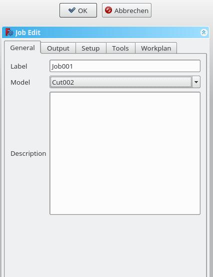
* Label: The label of the Job as displayed in the tree view. |
|||
The Job GUI dialog box has five horizontally aligned tabs: {{MenuCommand|General}}, {{MenuCommand|Output}}, {{MenuCommand|Setup}}, {{MenuCommand|Tools}}, and {{MenuCommand|Workplan}}. The user can at any time utilize the {{Button|OK}} or {{Button|Cancel}} options within the dialog. |
|||
* Model: The Base Object which defines by its shape the paths of the job. If it is a Part Design object it is usually the Body which you select here. If you have an element selected in the tree ''before'' you click the "Add Job" icon that element is already entered here. You can change it by selecting a different element from the dropdown menue. |
|||
* Description: You can add some notes to the job here. Notes are only for your information and have no effect on the path. |
|||
==General== <!--T:7--> |
|||
== Output == |
|||
</translate> |
|||
[[File:Job 2.jpg]] |
|||
[[File:Job_1.jpg]] |
|||
<translate> |
|||
<!--T:9--> |
|||
* '''Output File''': Set the name and the storage folder of the G-code output file. |
|||
* ''' |
* '''Label''': The label of the Job as displayed in the tree view. |
||
* '''Model''': The Base Object which defines by its shape the paths of the job. If it is a Part Design object, it is usually the Body you select here. If you have an element selected in the tree ''before'' you click the "Add Job" icon that element is already entered here. You can change it by selecting a different element from the dropdown menu. |
|||
* '''Arguments''': here you can add some arguments for the postprozessor if needed. |
|||
* '''Description''': You can add some notes to the job here. Notes are only for your information and have no effect on the path. |
|||
== Output == <!--T:10--> |
|||
==Post Processing== |
|||
The Path Workbench stores the information about the tools and the paths internally in a generalized form. Since different machines use different dialects of GCodes the Code generation process is separated from the Path Workbench. There are several post processors predefined - e.g. a linux_cnc post processor - or you can add your own, which usually will be based on one of the existing post processors. |
|||
</translate> |
|||
===Post Processor Properties=== |
|||
[[File:Job_2.jpg]] |
|||
<translate> |
|||
<!--T:12--> |
|||
*{{PropertyData|Output File}}: Specifies the default file to which the generated GCode will be written. If it is left empty you will be asked on GCode generation to select a filename. |
|||
* '''Output File''': Set the name, extension, and the file path of the G-Code output. You can use the following placeholders: |
|||
*{{PropertyData|Post Processor}}: Select the post processor of your choice. You are offered all post processors from the distribution plus those from your macro directory. The post processor files are recognized by their name, which must have the form ..._post.py, e.g. linuxcnc_post.py. If you want to see only a subset of the post processors you can configure the list in the Preferences->Path dialog. |
|||
** '''%D''' directory of the active document |
|||
*{{PropertyData|Post Processor Arguments}}: Some of the post processors can be configured with additional command line arguments. See the documentation of the post processor of your choice. Depending on the selected post processor there might be a hint shown, when you move the mouse over this field |
|||
** '''%d''' name of the active document (without extension) |
|||
** '''%M''' user macro directory |
|||
** '''%j''' name of the job |
|||
<!--T:24--> |
|||
* '''Processor''': Select the [[CAM_Post|postprocessor]] for your machine. |
|||
* '''Arguments''': Add arguments for the [[CAM_Post|postprocessor]] as needed. |
|||
==Setup== <!--T:13--> |
|||
</translate> |
|||
[[File:Job_3.jpg]] |
|||
<translate> |
|||
<!--T:15--> |
|||
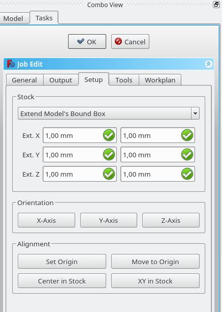
* '''Stock''': set the size and shape of the raw material. |
|||
* '''Orientation''': Selected Edge or Face is used to orient Base or Stock accordingly. |
|||
* '''Alignment''': select a Vertex to set origin or move Base or Stock |
|||
==Tools== <!--T:16--> |
|||
</translate> |
|||
[[File:Job_4.jpg]] |
|||
<translate> |
|||
<!--T:18--> |
|||
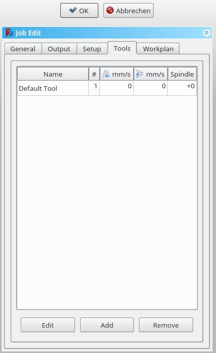
Add the tool(s) from your [[CAM_ToolLibraryEdit|Tooltable]] that you need for the operations at this job. |
|||
<!--T:19--> |
|||
After adding a tool, you can set/change the feedrate and spindle speed if you need a different feedrate in this job. |
|||
A change here doesn't change the parameters stored in the tooltable. |
|||
<!--T:20--> |
|||
You can delete the default tool if you have your own tool added. |
|||
==Workplan== <!--T:21--> |
|||
</translate> |
|||
[[File:Job_5.jpg]] |
|||
<translate> |
|||
<!--T:23--> |
|||
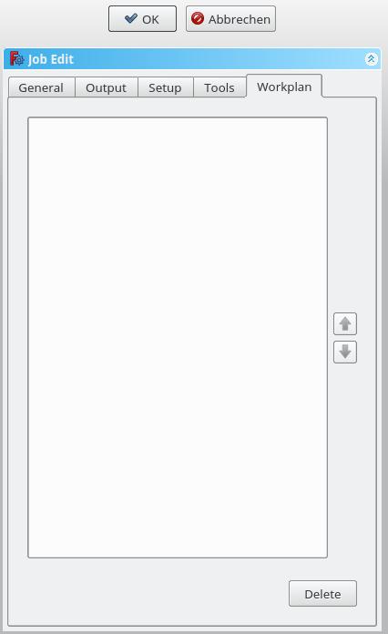
If you have a job that contains more than one path operation, you can determine in which order the operations should be done. |
|||
To reorder, select an operation and push the up or down button. |
|||
<!--T:26--> |
|||
{{Docnav |
|||
| |
|||
|[[CAM_Post|Post]] |
|||
|[[CAM_Workbench|CAM]] |
|||
|IconL= |
|||
|IconR=CAM_Post.svg |
|||
|IconC=Workbench_CAM.svg |
|||
}} |
|||
</translate> |
|||
{{CAM_Tools_navi{{#translation:}}}} |
|||
{{Userdocnavi{{#translation:}}}} |
|||
Latest revision as of 22:28, 16 March 2024
|
|
| Menu location |
|---|
| CAM → Job |
| Workbenches |
| CAM |
| Default shortcut |
| P J |
| Introduced in version |
| - |
| See also |
| CAM Post, CAM Postprocessor Customization |
Description
The Job tool creates a new Job object in the active document. The Job object contains the following information:
- A list of Tool-Controller definitions, specifying the geometry, Feeds, and Speeds for the Path Operations Tools.
- A Workflow sequential list of Path Operations.
- A Base Body—a clone used for offset.
- A Stock, representing the raw material that will be milled to CAM Workbench.
- A SetupSheet, containing inputs used by the Path Operations, including static values and formulas.
- Configuration parameters specifying the output G-Code job's destination path, file name, and extension, and the postprocessor (used to generate the appropriate dialect for the target CNC Controller, and customize Units, Tool Changes, Parking, etc.).
Usage
- There are several ways to invoke the command:
- Press the
CAM Job button.
- Select the CAM →
Job option from the menu.
- Use the keyboard shortcut: P then J.
- Press the
The Job GUI dialog box has five horizontally aligned tabs: General, Output, Setup, Tools, and Workplan. The user can at any time utilize the OK or Cancel options within the dialog.
General
- Label: The label of the Job as displayed in the tree view.
- Model: The Base Object which defines by its shape the paths of the job. If it is a Part Design object, it is usually the Body you select here. If you have an element selected in the tree before you click the "Add Job" icon that element is already entered here. You can change it by selecting a different element from the dropdown menu.
- Description: You can add some notes to the job here. Notes are only for your information and have no effect on the path.
Output
- Output File: Set the name, extension, and the file path of the G-Code output. You can use the following placeholders:
- %D directory of the active document
- %d name of the active document (without extension)
- %M user macro directory
- %j name of the job
- Processor: Select the postprocessor for your machine.
- Arguments: Add arguments for the postprocessor as needed.
Setup
- Stock: set the size and shape of the raw material.
- Orientation: Selected Edge or Face is used to orient Base or Stock accordingly.
- Alignment: select a Vertex to set origin or move Base or Stock
Tools
Add the tool(s) from your Tooltable that you need for the operations at this job.
After adding a tool, you can set/change the feedrate and spindle speed if you need a different feedrate in this job. A change here doesn't change the parameters stored in the tooltable.
You can delete the default tool if you have your own tool added.
Workplan
If you have a job that contains more than one path operation, you can determine in which order the operations should be done. To reorder, select an operation and push the up or down button.
- Project Commands: Job, Post Process, Check the CAM job for common errors, Export Template
- Tool Commands: Inspect CAM Commands, CAM Simulator, Finish Selecting Loop, Toggle the Active State of the Operation, ToolBit Library editor, ToolBit Dock
- Basic Operations: Profile, Pocket Shape, Drilling, Face, Helix, Adaptive, Slot, Engrave, Deburr, Vcarve
- 3D Operations: 3D Pocket, 3D Surface, Waterline
- CAM Modification: Copy the operation in the job, Array, Simple Copy
- Specialty Operations: Thread Milling
- Miscellaneous: Area, Area workplane
- ToolBit architecture: Tools, ToolShape, ToolBit, ToolBit Library, ToolController
- Additional: Preferences, Scripting
- Getting started
- Installation: Download, Windows, Linux, Mac, Additional components, Docker, AppImage, Ubuntu Snap
- Basics: About FreeCAD, Interface, Mouse navigation, Selection methods, Object name, Preferences, Workbenches, Document structure, Properties, Help FreeCAD, Donate
- Help: Tutorials, Video tutorials
- Workbenches: Std Base, Arch, Assembly, CAM, Draft, FEM, Inspection, Mesh, OpenSCAD, Part, PartDesign, Points, Reverse Engineering, Robot, Sketcher, Spreadsheet, Surface, TechDraw, Test Framework
- Hubs: User hub, Power users hub, Developer hub


