Basic Sketcher Tutorial/ro: Difference between revisions
No edit summary |
(Created page with "Ar trebui să finalizați cu o schiță complet constrânsă. Aceasta poate fi confirmată prin observarea modificării culorii tuturor curbelor.") |
||
| Line 109: | Line 109: | ||
# Set the center circle radius to 10 mm. |
# Set the center circle radius to 10 mm. |
||
Ar trebui să finalizați cu o schiță complet constrânsă. Aceasta poate fi confirmată prin observarea modificării culorii tuturor curbelor. |
|||
You should end up with a fully constrained sketch. It can be confirmed by noticing the change in color of all curves. |
|||
<div class="mw-translate-fuzzy"> |
<div class="mw-translate-fuzzy"> |
||
Revision as of 18:32, 6 March 2019
| Topic |
|---|
| Sketcher |
| Level |
| Beginner |
| Time to complete |
| 10 minutes |
| Authors |
| Drei |
| FreeCAD version |
| 0.16 or above |
| Example files |
| See also |
| None |
Introducere
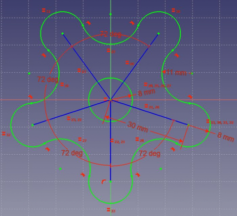
Acest tutorial are rolul de a introduce cititorul în fluxul de lucru de bază al aplicației Sketcher Workbench. Vom crea o schiță similară celei prezentate mai jos.
Atelierul de lucru Sketcher există ca modul independent, dar este accesibil și din cadrul PartDesign Workbench atunci când este necesar să creați un profil.
Cerințe
- Versiunea FreeCAD 0.16 sau mai recentă
Procedură
Crearea unei Sketch
- Creați un nou document
- Comutați la Sketcher Workbench utilizând meniul contextual drop-down menu sau făcând click pe View menu > Workbench > Sketcher.
- Selectați
 New sketch
 - Ar trebui să vedeți un dialog care vă solicită să alegeți orientarea schiței și să oferiți o compensare. Nu vom folosi offset și vom folosi planul implicit
- Faceți clic pe OK și putem începe să construim schița
Suntem acum în mediul Sketcher. În cadrul acestuia, putem folosi majoritatea instrumentelor disponibile în acest atelier de lucru.
In the Combo View, expand the option Edit controls and make sure Autoconstraints are enabled.
Creating geometry
Sketcher construction geometry
Construction geometry is used as guides for the creation of complex profiles. To access it, we need to enable Construction mode .
- Selectați
 Construction Mode
 - Select
 Line by 2 point
 - Apropiați origin point din schiță, punctul ar trebui să evidențieze lângă cursorul această pictogramă
 va apărea.
 - Selectați punctul și extindeți linia în diagonală până la o lungime arbitrară.
- Repetați această procedură până când creați cinci linii de construction. Asigurați-vă că păstrați-le pe toate diagonale.
- Pentru a ieși din modul construcție, doar faceți click din nou pe
 Construction Mode
Sketcher geometry
Sketcher geometry is used to create the closed profiles required to perform 3D operations in the PartDesign workbench.
- Select
 Circle
 - Position its centerpoint on the origin of the sketch.
- Extend the circumference to an arbitrary length.
- Select
 Arc
Arc - Approach the endpoint of one of the construction lines.
- Set the centerpoint' of the arc to be coincident with the endpoint.
- Select an arbitrary location of your cursor to be set as the beginning of the arc, by clicking once.
- Extend the arc an arbitrary amount, making sure the circumference opens outward (the empty space is facing towards the circle you created earlier).
- Repeat these steps for each construction line.
- Create an arc between each pair of the previous arcs, with their circumference pointing towards the circle.
We have now created the basic elements for our profile.
Constraints
Constraints are used to constrain the Degrees of Freedom of points and curves within sketcher.
Geometric Constraints
They are used to establish relations between points and curves without the use of dimensions.
- Select all five construction lines.
- Select
 Equal Length
- Select all five arcs centered on an endpoint of a line.
- Select
 Equal Length
 - Repeat for all five arcs that are not centered on an endpoint.
- Select the construction line that is closest to the vertical axis.
- Select
 Vertical
- Select the endpoint of an arc and the endpoint closest to it.
- Select
 Tangent
 - Repeat for each endpoint, until a closed profile is created.
As of this step, we have now created a closed profile that can be adjusted with the desired dimensions.
Datum Constraints
These are used to specify the distance between points in a particular direction and the dimensions of curves.
- Select the vertically constrained construction line.
- Select
 Vertical Distance
 - Set the length to 30 mm.
- Select the vertical construction line and the line closest to it
- Select
 Internal Angle
 - Set the angle to 72°
- Repeat the same procedure for each pair of adjacent lines.
- Select one of the arcs centered on the endpoint of a line.
- Select
 Radius
 - Set the radius to 8 mm.
- Do the same for an arc not centered on an endpoint. Set the radius to 11 mm.
- Set the center circle radius to 10 mm.
Ar trebui să finalizați cu o schiță complet constrânsă. Aceasta poate fi confirmată prin observarea modificării culorii tuturor curbelor.
We are now finished with the basic workflow for the Sketcher Module.
Lectură Suplimentară
- Pentru a înțelege mai mult asupra atelierului, a se vedeaSketcher Workbench.
