Basic Sketcher Tutorial/it: Difference between revisions
Renatorivo (talk | contribs) (Created page with "Nella '''Vista combinata''', espandere le opzioni '''Edit controls''' e abilitare gli '''Autovincoli'''.") |
Renatorivo (talk | contribs) (Created page with "==== Creare la geometria ==== ===== La geometria di costruzione dello schizzo ===== La geometria di costruzione viene utilizzato come guida per creare dei profili complessi. P...") |
||
| Line 29: | Line 29: | ||
Nella '''Vista combinata''', espandere le opzioni '''Edit controls''' e abilitare gli '''Autovincoli'''. |
Nella '''Vista combinata''', espandere le opzioni '''Edit controls''' e abilitare gli '''Autovincoli'''. |
||
==== |
==== Creare la geometria ==== |
||
===== |
===== La geometria di costruzione dello schizzo ===== |
||
La geometria di costruzione viene utilizzato come guida per creare dei profili complessi. Per accedervi, è necessario attivare la modalità '''Costruzione'''. |
|||
Construction geometry is used as guides for the creation of complex profiles. To access it, we need to enable '''Construction mode '''. |
|||
# Select [[Image:Sketcher_ToggleConstruction.png|32px]] [[Sketcher_ToggleConstruction|Construction Mode]] |
# Select [[Image:Sketcher_ToggleConstruction.png|32px]] [[Sketcher_ToggleConstruction|Construction Mode]] |
||
Revision as of 22:01, 28 October 2015
| Argomento |
|---|
| {{{Topic}}} |
| Livello di difficoltà |
| Base |
| Tempo di esecuzione |
| 10 minuti |
| Autori |
| Drei |
| Versione di FreeCAD |
| 0.16 o superiore |
| Files di esempio |
| Vedere anche |
| Nessuno |
Introduzione
Questo tutorial ha lo scopo di introdurre il lettore al flusso di lavoro di base dell'ambiente Schizzo.
L'ambiente Sketcher esiste come modulo autonomo, ma è accessibile anche dall'ambiente PartDesign quando è necessario per creare un profilo.
Requisiti
- FreeCAD versione 0.16 o superiore
Procedura
Creare uno Schizzo
- Creare un nuovo documento
- Passare nell'ambiente Sketcher
- Selezionare
 Nuovo schizzo
Ora siamo all'interno dell'ambiente Sketcher. Al suo interno, siamo in grado di utilizzare la maggior parte degli strumenti disponibili in questo ambiente.
Nella Vista combinata, espandere le opzioni Edit controls e abilitare gli Autovincoli.
Creare la geometria
La geometria di costruzione dello schizzo
La geometria di costruzione viene utilizzato come guida per creare dei profili complessi. Per accedervi, è necessario attivare la modalità Costruzione.
- Select
 Construction Mode
 - Select
 Line by 2 point
 - Approach the origin point in the sketch, the point should highlight and near your cursor this icon
 will appear.
 - Select the point and extend the line diagonally up to an arbitrary length.
- Repeat this procedure until you've created five construction lines. Be sure to keep all of them diagonal.
- To exit construction mode, simply click again on
 Construction Mode
Sketcher geometry
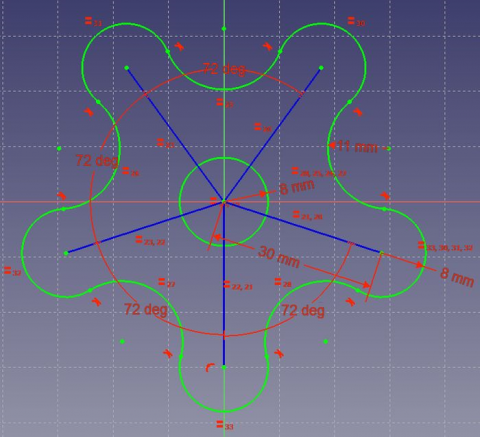
Sketcher geometry is used to create the closed profiles required to perform 3D operations in the PartDesign workbench.
- Select
 Circle
 - Position its centerpoint on the origin of the sketch.
- Extend the circumference to an arbitrary length.
- Select
 Arc
Arc - Approach the endpoint of one of the construction lines.
- Set the centerpoint' of the arc to be coincident with the endpoint.
- Select an arbitrary location of your cursor to be set as the beginning of the arc, by clicking once.
- Extend the arc an arbitrary amount, making sure the circumference opens outward (the empty space is facing towards the circle you created earlier).
- Repeat these steps for each construction line.
- Create an arc between each pair of the previous arcs, with their circumference pointing towards the circle.
We have now created the basic elements for our profile.
External Geometry
When a 3D element has been created it is possible to create references to it within a sketch.
- Select
 External Geometry.
 - Approach the element that you wish to reference, the edge of a Pad for example.
- Click on it
- New elements of a different color should appear on the sketch in the location of the feature you wish to reference.
Constraints
Constraints are used to constrain the Degrees of Freedom of points and curves within sketcher.
Geometric Constraints
They are used to establish relations between points and curves without the use of dimensions.
- Select all five construction lines.
- Select
 Equal Length
- Select all five arcs centered on an endpoint of a line.
- Select
 Equal Length
 - Repeat for all five arcs that are not centered on an endpoint.
- Select the construction line that is closest to the vertical axis.
- Select
 Vertical
- Select the endpoint of an arc and the endpoint closest to it.
- Select
 Tangent
 - Repeat for each endpoint, until a closed profile is created.
As of this step, we have now created a closed profile that can be adjusted with the desired dimensions.
Datum Constraints
These are used to specify the distance between points in a particular direction and the dimensions of curves.
- Select the vertically constrained construction line.
- Select
 Vertical Distance
 - Set the length to 30 mm.
- Select the vertical construction line and the line closest to it
- Select
 Internal Angle
 - Set the angle to 72°
- Repeat the same procedure for each pair of adjacent lines.
- Select one of the arcs centered on the endpoint of a line.
- Select
 Radius
 - Set the radius to 8 mm.
- Do the same for an arc not centered on an endpoint. Set the radius to 11 mm.
- Set the center circle radius to 10 mm.
You should end up with a fully constrained sketch. It can be comfirmed by noticing the change in color of all curves.
We are now finished with the basic workflow for the Sketcher Module.
Further Reading
- To understand more about the workbench, see Sketcher Workbench
