Thread for Screw Tutorial/de: Difference between revisions
Wurstwasser (talk | contribs) No edit summary |
Wurstwasser (talk | contribs) No edit summary |
||
| Line 28: | Line 28: | ||
=== Methode 3: Ein vertikales Profil entlang einer Kurve extrudieren === |
=== Methode 3: Ein vertikales Profil entlang einer Kurve extrudieren === |
||
Die Idee ist sehr einfach: Erstellen eines Profils und anschließendes Extrudieren ([[Part Sweep/de|Sweep]] [[Image:Part_Sweep.png|16px]]) des Profils entlang einer helixförmigen Kurve ([[Part Helix/de|Helix]] [[Image:Part_Helix.png|16px]]). Dabei müssen die Checkboxen ''Erzeuge Volumenkörper'' und ''Frenet'' aktiviert sein, damit später noch Bool'sche Operationen wie z.B. ''Vereinigen'' [[Image:Part_Fuse.png|16px]] oder ''Ausschneiden'' [[Image:Part_Cut.png|16px]] auf das Ergebnis anwendbar sind und zudem keine Verdrillungen entstehen. |
|||
Das Resultat ist eine Spule mit dem gewünschten Profil. Um daraus ein Gewinde zu machen, muss das Ergebnis der Operation mit einem Zylinder oder einer Bohrung vereinigt werden. Mit weiteren Bool'schen Operationen können zudem die abrupten Enden der Spule beseitigt werden. |
Das Resultat ist eine Spule mit dem gewünschten Profil. Um daraus ein Gewinde zu machen, muss das Ergebnis der Operation mit einem Zylinder oder einer Bohrung vereinigt werden. Mit weiteren Bool'schen Operationen können zudem die abrupten Enden der Spule beseitigt werden. |
||
Revision as of 18:43, 12 January 2016
| Topic |
|---|
| {{{Topic}}} |
| Level |
| Fortgeschrittene |
| Time to complete |
| Authors |
| DeepSOIC, Murdic |
| FreeCAD version |
| 0.14 oder neuer (je nach Methode) |
| Example files |
| See also |
| None |
Einleitung
Dieses Tutorial beschreibt mehrere Vorgehensweisen zum Modellieren von Gewinden in FreeCAD.
Gewinde in FreeCAD zu modellieren ist nicht empfehlenswert, weil die notwendigen Berechnungen das Programm stark beanspruchen und den Speicherverbrauch in die Höhe treiben. Bereits ein einziges Gewinde in einer FreeCAD-Datei kann die Dateigröße auf mehrere Megabyte erhöhen. Es gibt jedoch Situationen, in denen sich eine präzise Modellierung von Gewinden nicht vermeiden lässt und für diese Situationen ist dieses Tutorial gedacht.
Methode 0: Das Gewinde aus einer Bibliothek beziehen
Bereits fertiggestellte Modelle anderer Personen zu verwenden ist besonders einfach und zeitsparend. Mit dem Macro BOLTS können verschiedene standardisierte Bauteile aus der Blibliothek BOLTS in FreeCAD eingefügt werden.
Methode 1: Verwendung von Macros
Mit dem beliebten Macro Screw Maker, erstellt von ulrich1a, oder dem zusätzlichen Arbeitsbereich Fasteners Workbench, erstellt von shaise (link to GitHub), können oftmals passende dreieckige Standardgewinde generiert werden.
Methode 2: Schummeln mit gestapelten Scheiben
Dies ist ein guter Weg, um Gewinde grob zu visualisieren und dabei die Geometrie möglichst einfach zu halten. Da jedoch kein tatsächliches Gewinde erzeugt wird, ist diese Methode für herzustellende Bauteile normalerweise ungeeignet.
Die Idee hierbei ist, ein nicht-schraubenförmiges Gewinde zu erzeugen und scheibenförmig zu stapeln. Solch ein Pseudogewinde ist auf den ersten Blick nur schwer von einem tatsächlichen Gewinde zu unterscheiden und lässt sich deshalb in bestimmten Situationen (z.B. FEM-Simulationen) verwenden.
Methode 3: Ein vertikales Profil entlang einer Kurve extrudieren
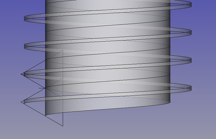
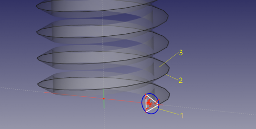
Die Idee ist sehr einfach: Erstellen eines Profils und anschließendes Extrudieren (Sweep ![]() ) des Profils entlang einer helixförmigen Kurve (Helix
) des Profils entlang einer helixförmigen Kurve (Helix ![]() ). Dabei müssen die Checkboxen Erzeuge Volumenkörper und Frenet aktiviert sein, damit später noch Bool'sche Operationen wie z.B. Vereinigen
). Dabei müssen die Checkboxen Erzeuge Volumenkörper und Frenet aktiviert sein, damit später noch Bool'sche Operationen wie z.B. Vereinigen ![]() oder Ausschneiden
oder Ausschneiden ![]() auf das Ergebnis anwendbar sind und zudem keine Verdrillungen entstehen.
auf das Ergebnis anwendbar sind und zudem keine Verdrillungen entstehen.
Das Resultat ist eine Spule mit dem gewünschten Profil. Um daraus ein Gewinde zu machen, muss das Ergebnis der Operation mit einem Zylinder oder einer Bohrung vereinigt werden. Mit weiteren Bool'schen Operationen können zudem die abrupten Enden der Spule beseitigt werden.
Tricks to success
Rule 1. The sweep must not self-intersect. A self-intersecting sweep is an invalid solid. Attempts to fuse it or cut it are very likely to fail. Nevertheless, this may be OK for 3d-printing and visualization purposes to leave the coil and the cylinder unfused (intersecting).
Rule 2. Remember that helix in FreeCAD is an imprecise thing. As a consequence, a cylinder made to mate with the thread precisely is very likely to fail to fuse to the thread. In general, avoid geometry coincident to elements of the sweep, such as tangent faces, edges tangent to faces they are not connected to, coincident and tangent edges, etc.
Tip 1. The radius of the helix does not matter (unless the helix is tapered). All that matters is the pitch and the height of the helix. This means that you can use a generic helix to generate a number of threads with equal pitch.
Tip 2. Keep it short (low number of turns). Long threads tend to fail in Boolean operations. Consider stacking the thread from short pieces using Draft Array, if a long thread proves problematic.
Pros and cons
+ Very natural way of defining thread profile
+ easy to understand
+ no problems with mesh generation, unlike method 4
- due to invalidity of self-intersecting sweeps, it is next to impossible to generate a gapless thread (that is, with no cylindrical faces at the outer or inner sides of the thread)
- Boolean operations are required to obtain meaningful results. These take long time and fail often.
- Threads with high number of turns are problematic.
Method 4. Sweeping a horizontal profile
Idea
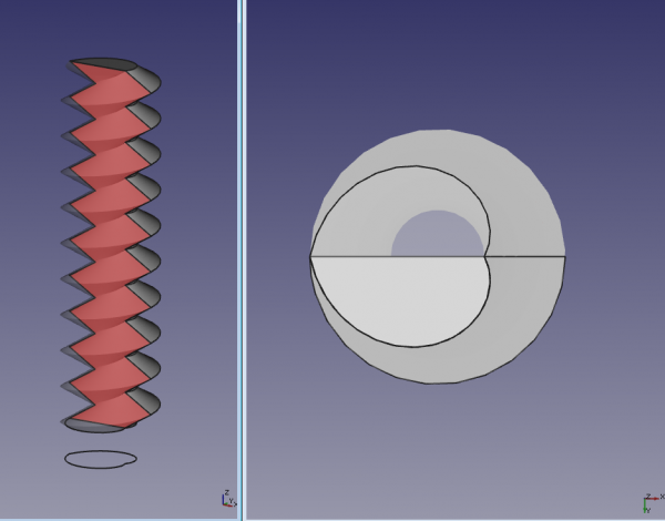
The idea is to sweep a horizontal cross-section of the thread along the helix. The main problem here is figuring out, what profile to use to obtain a certain thread.
If one uses a circle as a horizontal profile (the circle has to be placed off the origin, that offset defines the depth of the thread), thread profile will be sinusoidal.
To obtain a standard sawtooth profile, a pair of mirrored archimedean spirals need to be fused into a wire. The resulting figure is a heart shape, which becomes barely distinguishable from a circle when the depth of the thread is small compared to its diameter (this is why such a "thick" thread is shown on the picture above).
Generating the profile
Figuring out, what the horizontal profile needs to be made for obtaining a certain vertical profile is not easy. For simple cases like triangular or trapezoidal, it can be constructed manually. Alternatively, it can be constructed by creating a short thread with method 3, and getting a slice of it by doing a common between a horizontal plane face and the thread.
Profile for triangular thread
- Create a spiral (archimedian) in XY plane.
- Set number of turns to 0.5,
- the radius to the inner radius of the thread (outer radius will be this + depth of cut)
- and growth to double the depth of cut of the thread.
- Part Mirror the spiral against XY plane
- Part Fuse the spiral and the mirror to obtain a closed wire, shaped like a heart. Done!
Profile for arbitrary cross-section
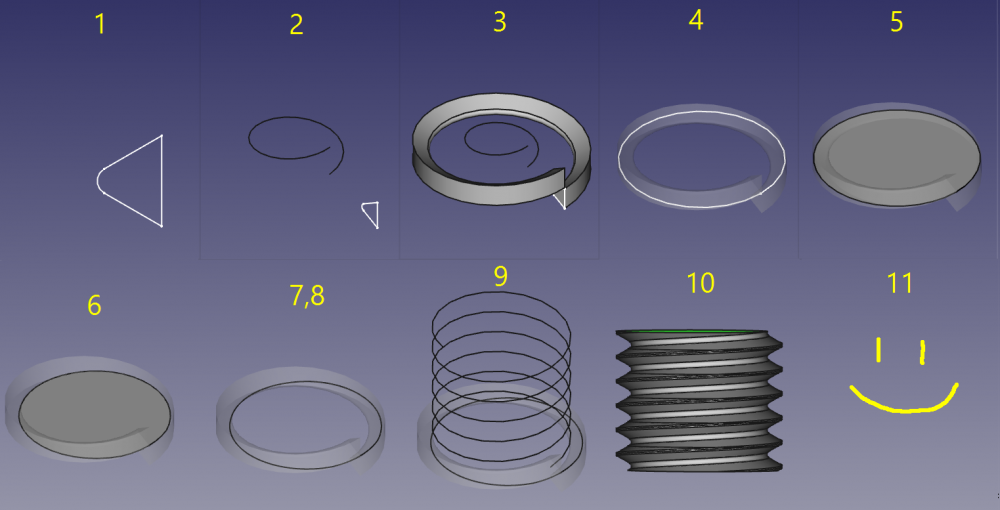
- make a (vertical) cut profile. Make sure that the height of the sketch matches the pitch of the thread you need.
- make a helix1 with height identical to the pitch and the pitch identical to the thread pitch and a helix radius of 0.42*nominal diameter of the thread.
- Sweep the cut profile along the helix1. Set make solid and frenet to true.
- Make a circle with nominal radius of the thread in the x-y-plane.
- Make a face from the circle. (Part-workbench: advanced utility to create shapes, or Draft Upgrade then MakeFace = true)
- cut the face with the sweep profile
- make a clone from the cut (Draft workbench)
- Downgrade the clone in order to get a wire. (Draft workbench) This wire is the horizontal profile needed for this method.
- Make a helix with radius of nominal radius of the thread and a pitch of the thread and the height of the needed thread.
- Sweep the wire along the helix. Set solid and frenet to true.
You are done.
Credit: step-by-step guide from a forum post by Ulrich1a, slightly modified.
The steps are also shown in action on this video by Gaurav Prabhudesai: http://www.youtube.com/watch?v=fxKxSOGbDYs
Pros and cons
+ A ready-to-use thread-on-a-rod solid shape is created by the sweep directly.
+ Less or even no Boolean operations required, generation speed is very high compared to Method 3.
+ Thread ends are nicely cut straight away
+ Long threads are not a problem, unless a Boolean operation is needed. Otherwise, it is not going to be much better than Method 3.
+ Gapless threads are not a problem.
- Defining thread profile is complicated.
- Standard mesher generates ugly meshes, which can lead to problems. Other meshers are better, Mefisto seems to give the best results.
- large memory footprint [1]
Method 5. Lofting between helical extruded faces
Idea
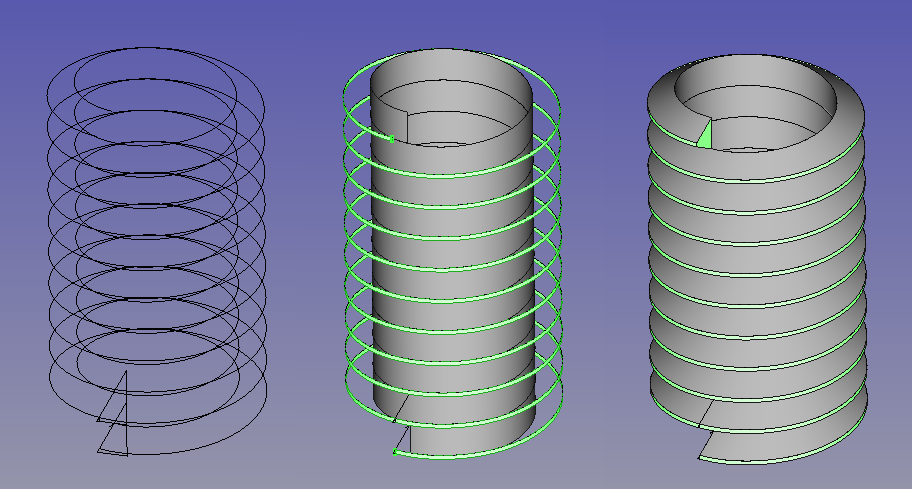
Helical splines will extrude coaxial faces that are able to be lofted, while FreeCAD's parametric helix won't. It takes two helical splines to define a thread. Those two can be scaled from a library spline, then located and extruded appropriately to get the form right.
FreeCAD's parametric helixes aren't truly helical, but helical b-splines aren't difficult to lay out. One manual method is to array dodecagons (12-sided polygons) with 5mm radius/10mm diameter at 1/12mm (0.08333.mm) z intervals and trace splines from vertex to vertex in ascending and rotating order, and to consider doing it once with, say, 10 turns, so that that spline can be re-used as a library file for import and reuse. It's convenient to use 10mm diameter/1mm pitch for ease of scaling. If you are doing it manually, drawing a Dwire and then converting it to a b-spline is easier than drawing a spline. Dwires don't have curvature computed while being drawn, so they follow the cursor and snap more obediently.
Once the splines are scaled to the right size and located so that the loft will have the right included angle between the thread flanks, they're extruded along their axis, a pitch length's worth for the inner spline, the outer pitch/8.
ISO and other threads have relieved, ie flat, inner and outer edges rather than sharp, which suits FreeCAD users with this method, because we can loft to the helical face at the nominal fastener size, while an inner face can't be lofted to an outer edge spline because a face is a closed profile, a spline is open. ISO standard says the nominal size of external threads have a face width pitch/8. The picture shows how the geometry is arranged, and the helical faces that result. Then, loft between the faces, and then a cylinder that gives the inner helical face, which ISO puts at pitch/4 width, is added to the threads.
This method produces reliable solids that boolean properly. While it doesn't produce "parametric" screw threads in standard sizes in the sense of having simple access to form by fastener size, it's an easy way of producing an accurate library for reuse, and models of specialised forms like ACME, or Archimedian screws, are also uncomplicated as one-offs.


