TechDraw MaßDurchmesser
|
TechDraw Durchmesserbemaßung |
| Menüeintrag |
|---|
| TechDraw → Ein neues Durchmessermaß in die gewählte Ansicht einfügen |
| Arbeitsbereich |
| TechDraw |
| Standardtastenkürzel |
| Standardtastenkürzel |
| Eingeführt in Version |
| - |
| Siehe auch |
| Siehe auch |
Description
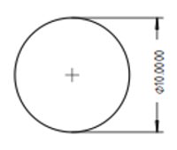
The Dimension Diameter tool adds a diameter dimension to a View. The dimension may be applied to any circular in the drawing. The distance will initially be the projected distance (ie as shown on the drawing), but this may be changed to the actual 3D distance using the Link Dimension ![]() tool.
tool.

How to use
- Select a circular edge in the drawing. (Note some arcs which appear to be circular are actually ellipses or BSplines. You cannot make a diameter dimension in these cases)
- Press the File:Dimension Diameter.png Dimension Diameter button
- A dimension will be added to the View. The dimension may be dragged to the desired position.
Options
None.
Properties
Scripting
Diameter dimensions can be added to Pages using Python.
dim1 = FreeCAD.ActiveDocument.addObject('TechDraw::DrawViewDimension','Dimension')
dim1.Type = "Diameter"
dim1.References2D=[(view1, 'Edge1')]
rc = page.addView(dim1)
Notes
- All Dimensions are extremely vulnerable to the infamous "topological naming" issue. It is not possible at this time to keep references to 2D (projected) or 3D (actual) geometrical objects in sync with changes in the model. It is recommended that Dimensions be added towards the end of the drawing creation process.