Sketcher Tutorium
Einleitung
Der Arbeitsbereich Sketcher ermöglicht das Erstellen von 2D-Objekten für die Verwendung in anderen Arbeitsbereichen (z.B. Part Design). Der Sketcher unterscheidet sich dabei von altmodischen Skizzierwerkzeugen. Dieser Unterschied soll im Folgenden am Beispiel eines Dreiecks gezeigt werden. Ein Dreieck ist im Allgemeinen vollständig definiert durch die Angabe von drei Werten aus der folgenden Liste: Seitenlänge, Winkel, Höhe, Flächeninhalt. Die einzige Ausnahme wären drei Winkel, weil die Größe nicht eindeutig festgelegt wäre.
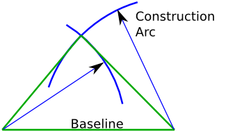
Um ein Dreieck mit drei Längenangaben zu konstruieren, muss wie folgt vorgegangen werden:
- Zeichnen einer Grundlinie (Länge 1)
- An beiden Enden der Grundlinie je einen Kreis zeichnen, dessen Radius einer der zwei verbliebenen Längen entspricht (Länge 2 und 3).
- Zwischen dem Schnittpunkt der beiden Kreise und ihren Mittelpunkten (Endpunkte der Grundlinie) weitere Linien zeichnen.
In der [Wikipedia] lässt sich eine Sammlung von Formeln finden, mit denen die verbliebenen Eigenschaften eines Dreiecks berechnet werden können. Diese werden benötigt, falls das Dreieck nicht auf grafischem Wege (wie oben), sondern durch Berechnung der richtigen Koordinaten festgelegt werden soll.
Der Arbeitsbereich Sketcher ist anders. Die gerade erwähnten Verfahren und Formeln werden nicht benötigt. Um diesen Unterschied zu verstehen, sollte am besten ein Dreieck mit dem Sketcher gezeichnet werden. Wie das geht, wird im nachfolgenden Abschnitt beschrieben.
Erster Entwurf: ein Dreieck
Zum Erstellen eines Entwurfs wird ein offenes Dokument benötigt. Falls keines vorhanden ist, dann klicken Sie auf das Icon für ein neues Dokument . Außerdem muss der Arbeitsbereich Sketcher aktiviert sein (Menü: Ansicht > Arbeitsbereich > Sketcher).
Eine neuer Entwurf wird erzeugt mit einem Klick auf ![]() (alternativ über das Menü Sketch > Skizze erstellen). Im daraufhin erscheinenden Dialog wird die Entwurfsebene im 3D-Raum ausgewählt. In diesem Fall ist diese Wahl unwichtig, also kann einfach OK angeklickt werden. Es entsteht ein neuer Entwurf, der im Bearbeitungsmodus angezeigt wird. Zu sehen ist nun ein Gitter mit einem 2D-Koordinatensystem, dessen Nullpunkt als roter Punkt in der Fenstermitte erscheint.
(alternativ über das Menü Sketch > Skizze erstellen). Im daraufhin erscheinenden Dialog wird die Entwurfsebene im 3D-Raum ausgewählt. In diesem Fall ist diese Wahl unwichtig, also kann einfach OK angeklickt werden. Es entsteht ein neuer Entwurf, der im Bearbeitungsmodus angezeigt wird. Zu sehen ist nun ein Gitter mit einem 2D-Koordinatensystem, dessen Nullpunkt als roter Punkt in der Fenstermitte erscheint.
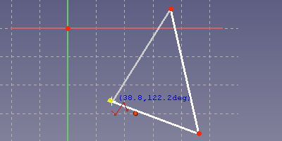
Im Arbeitsbereich Sketcher ist es in Ordnung, zunächst ein beliebiges Dreieck mit dem Werkzeug Linienzug erstellen ![]() zu zeichnen und erst im Nachhinein seine Eigenschaften festzulegen. Jeder Klick mit dem Werkzeug auf die Skizze erzeugt einen Eckpunkt. Zuletzt muss nochmals auf den ersten Eckpunkt geklickt werden, wobei dieser in gelb angezeigt wird, wenn der Mauszeiger richtig liegt. Dadurch wird sichergestellt, dass der erste und der letzte Eckpunkt übereinstimmen und das Profil geschlossen ist.
zu zeichnen und erst im Nachhinein seine Eigenschaften festzulegen. Jeder Klick mit dem Werkzeug auf die Skizze erzeugt einen Eckpunkt. Zuletzt muss nochmals auf den ersten Eckpunkt geklickt werden, wobei dieser in gelb angezeigt wird, wenn der Mauszeiger richtig liegt. Dadurch wird sichergestellt, dass der erste und der letzte Eckpunkt übereinstimmen und das Profil geschlossen ist.
Die Symbole, die beim Zeichnen unterhalb des Mauszeigers erscheinen, zeigen automatische Beschränkungen an. Sie werden vom Programm automatisch festgelegt, wenn an dieser Stelle ein Mausklick ausgeführt wird. Ein gelber Punkt zeigt dabei eine Koinzidenzbeschränkung (Verknüpfung) zwischen zwei Eckpunkten an.
Das so erzeugte Dreieck ist veränderbar. Die Eckpunkte können angeklickt und verschoben werden. Die Seiten werden dabei automatisch angepasst.
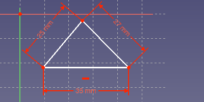
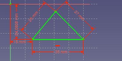
Die einzelnen Seiten können am einfachsten festgelegt werden, indem man sie per Mausklick auswählt und anschließend das Werkzeug Distanz festlegen ![]() verwendet. Es öffnet sich ein Dialog, der die Eingabe der Länge in Millimeter ermöglicht. Das nachfolgende Bild zeigt ein Dreieck mit den Seitenlängen 35 mm, 27 mm und 25 mm. Die Grundlinie wurde als Hoorizontale festgelegt, durch Auswahl und Verwendung des Werkzeugs Horizontal einschränken
verwendet. Es öffnet sich ein Dialog, der die Eingabe der Länge in Millimeter ermöglicht. Das nachfolgende Bild zeigt ein Dreieck mit den Seitenlängen 35 mm, 27 mm und 25 mm. Die Grundlinie wurde als Hoorizontale festgelegt, durch Auswahl und Verwendung des Werkzeugs Horizontal einschränken .
Diese Definitionen der Länge werden als Beschränkungen bezeichnet. Beschränkungen werden verwendet, um die Eigenschaften des Entwurfs nach seiner Erstellung präzise festzulegen. Der Arbeitsbereich Sketcher bietet einem alle notwendigen Beschränkungen, um ein beliebiges Dreieck vollständig zu definieren. Lediglich der Flächeninhalt kann nicht als Beschränkung festgelegt werden. Das Dreieck kann geändert werden, indem Beschränkungen geändert, entfernt oder hinzugefügt werden. Es folgt eine Liste von Dreiecken mit verschiedenen Eigenschaften. Das eigene Dreieck kann problemlos in jedes dieser Dreiecke umgewandelt werden.
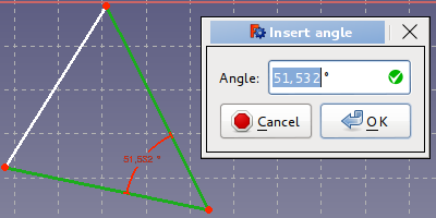
- Ein bis zwei Winkel vorgegeben: Zwei Seiten des Dreiecks müssen nacheinander angeklickt werden. Mit einem Klick auf Winkel festlegen
 öffnet sich ein Dialog, der die Festlegung des Winkel zwischen den beiden ausgewählten Seiten ermöglicht.
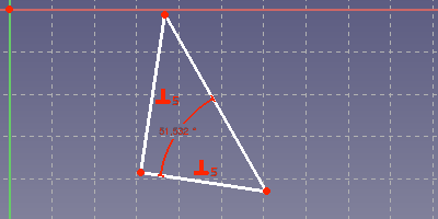
- Rechtwinkliges Dreieck: Zwei Seiten des Dreiecks auswählen und mit einem Klick auf Orthogonalität festlegen
 einen 90°-Winkel zwischen beiden Seiten festlegen.
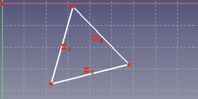
- Gleichseitiges Dreieck: Eine beliebige Seite erhält wie zuvor gezeigt eine feste Länge. Anschließend müssen alle drei Seiten ausgewählt und Gleichheit festlegen
 angeklickt werden.
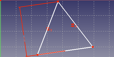
- Gleichschenkliges Dreieck mit fester Höhe: Zuerst die beiden Seiten, die gleich lang sein sollen, auswählen und wie zuvor auf Gleichheit festlegen
 klicken. Anschließend die dritte Seite und den ihr gegenüberliegenden Eckpunkt auswählen und Distanz festlegen
  verwenden, um die Höhe festzulegen.
Beschränkungen können entweder über das dazugehörige Icon oder über das Menü Sketch > Skizzen-Beschränkungen ausgewählt werden. Die können bei Bedarf wieder entfernt oder ihr Wert geändert werden (Doppelklick). Ein gegebenes Dreieck kann so auch im Nachhinein noch in ein anderes Dreieck geändert werden, indem die Beschränkungen geändert oder gewechselt werden. Der Arbeitsbereich Sketcher ist Bestandteil des parametrischen Modellierungsansatzes von FreeCAD, d.h. das eigene Entwürfe auch später noch geändert werden können.
Die oben gezeigten Dreiecke bestanden aus weissen Linien. Dies deutet darauf hin, dass der Entwurf noch Freiheitsgrade besitzt. Man kann dies überprüfen, indem man an den Eckpunkten oder Linien zieht und die Veränderung beobachtet. Das Bauteil ist dann noch nicht vollständig festgelegt, da es sonst grün dargestellt wäre.
Das gleichschenklige Dreieck besitzt noch eine undefinierte Seitenlänge (Grundlinie) und kann noch frei in der Zeichenebene bewegt werden.
Wenn die geometrischen Eigenschaften des Dreiecks festgelegt sind, so muss es immer noch einen festen Ort in der Zeichenebene bekommen. Der Ursprung des Koordinatensystems ist als roter Punkt im Schnittpunkt der Achsen (x: pink, y: grün) dargestellt. Am einfachsten ist die Festlegung der Dreiecksposition, indem ein Eckpunkt ausgewählt und die Beschränkung Sperren verwendet wird. Dadurch wird eine horizontale und eine vertikale Distanz zwischen dem ausgewählten Eckpunkt und dem Koordinatenursprung festgelegt. Falls nach wie vor ein Freiheitsgrad für die Rotation um den Ursprung vorhanden ist, so muss eine der Seiten entweder eine Beschränkung als Horizontale/Vertikale erhalten oder ein Winkel zwischen der Seite und einer Koordinatenachse festgelegt werden. Die nachfolgende Abbildung zeigt einen vollständig festgelegten Entwurf, in dem alle Linien und Punkte grün sind.
Mehr über Beschränkungen
Das Programm kennt die trigonometrischen Formeln in Wikipedia nicht. Stattdessen werden aus den gewählten Beschränkungen Gleichungssysteme für die 2D-Koordinaten erstellt und numerisch gelöst.
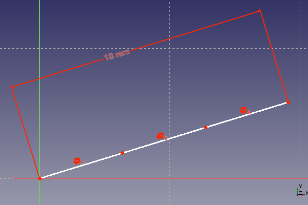
Auf diesem Wege können zahlreiche geometrische Problemstellungen gelöst werden. Es gibt jedoch auch einen Nachteil: Falls das Gleichungssystem mehrere Lösungen besitzt, kann das Ergebnis deutlich von den Erwartungen abweichen. Dies ist besonders nervig, wenn derselbe Entwurf für verschiedene Dimensionen genutzt werden soll. Das übliche Symptom dabei ist, dass nach dem Ändern einer Längenbeschränkung der Entwurf seine Gestalt vollkommen verändert. Ein einfaches Beispiel ist die Aufteilung einer Distanz in drei gleiche Teile. Das folgende Bild zeigt drei Linien mit den Beschränkungen Parallelität und Gleichheit, wobei die Gesamtlänge 10 mm beträgt.
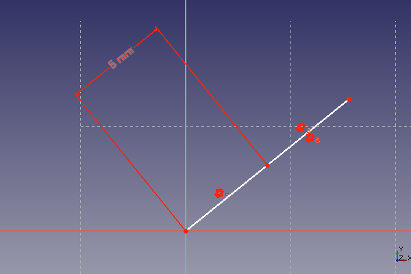
Dies funktioniert so lange, wie die Gesamtlänge einen bestimmten Schwellwert überschreitet. Wird der Wert unterschritten, so falten sich die drei Linien zusammen. Die Linienlänge ist nun gleich der Gesamtlänge und auch die Orientierung mancher Linien hat sich geändert. Die Beschränkungen sind dabei jedoch nach wie vor erfüllt, auch wenn das Ergebnis nicht den Erwartungen entspricht. Die folgende Abbildung zeigt dies, wobei die Gesamtlänge zunächst auf 1000 mm erhöht und dann auf 5 mm reduziert wurde.
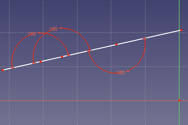
Die Lösung des Problems ist, statt der Parallelität der Linien einen 180°-Winkel zwischen ihnen festzulegen. Dann existiert nur eine numerische Lösung der mathematischen Problemstellung. Der Entwurf ist nun robust gegenüber größeren Änderungen der Gesamtlänge.
The 180°-constraint is a solution for a lot of problems. Some older versions of FreeCAD have problems to show the 180°-constraint in the sketcher plane. In most of the cases the 180°-arc is not shown as expected in the sketcher drawing plane. This is a known issue for FreeCAD before version 14.3613.
In case of several incremental dimensions in a straight line, it may be advisable to draw a zig-zag-line first and then set the 180°-constraints. This helps, not forgetting one, or setting one twice.
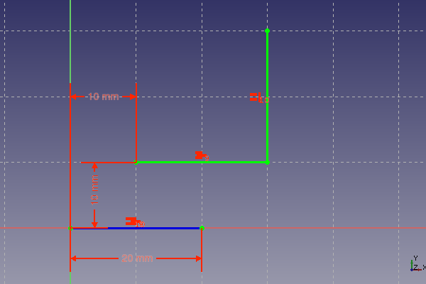
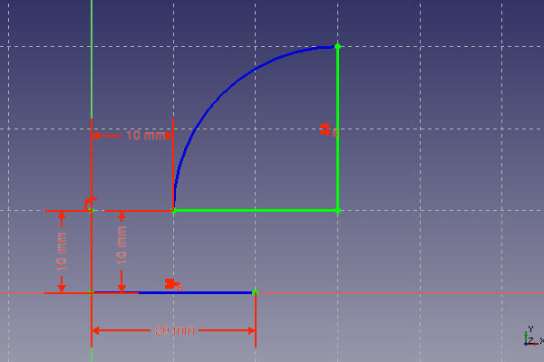
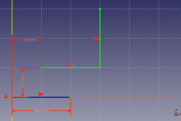
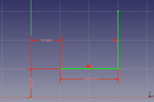
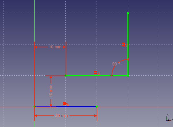
The following table shows some constraints combinations for the definition of a simple elbow. The combination was tested by enlarging the 10 mm length horizontal dimension to greater values until the elbow flips its orientation. The table documents for each shown constraint combination the changed length where the flipping occurs.
| Constraints Combination | Remarks |
|---|---|
|
Definition of length: Equality constraint for definition of length | |
|
Definition of length: Equality constraint for definition of vertical length, arc for definition of horizontal length. | |
|
Definition of length: Equality constraint for definition of length | |
|
Definition of length: Horizontal length defined with the general length constraint. Equality constraint for definition of vertical length. | |
|
Definition of length: Equality constraint for definition of length |
The test showed the following: larger changes of dimension constraints may cause a flipping of some lines of the sketch due to multiple solutions of the underlying system of equations. The only constraints that do preserve the orientation of the elements they are applied to, are the angle constraint and the horizontal and vertical dimension constraints. The differences between the other constraints regarding maintaining orientation are minor.
Recommendation: Use angle constraints and horizontal and vertical dimension constraints at critical places in order to make a sketch robust against dimension changes.
Problematic combination of constraints
Sometimes two or more constraints define the same property. An example can be made of two connected lines, where the connection point is the center point of a symmetry constraint for the endpoints of the lines. Those lines now have equal length and are parallel. All this is the consequence of the symmetry constraint.
What happens, if those two lines already have an equality constraint and a parallel constraint and the symmetry constraint is added too? Now the parallel property is defined by two constraints and the equal length is also defined by two constraints. In principle the underlying system of equations should have a solution. But there may be numerical problems. This can be tested by trying to move the lines. In most cases the lines are frozen, even if the sketcher still reports several degrees of freedom.
The above case shows a problem that seems to be difficult to solve for the sketcher programmers. So the user has to take care, to avoid such situations. Sketches with redundant constraints do behave unexpected and problematic. Symptoms of those redundant constraints are the above frozen state or reported redundant constraints after modifying a different object in the sketch.
In general the sketcher gives a warning, when redundant constraints are detected. But this detection mechanism seems not to work in all cases. When the problem is recognized, it can be avoided by just deleting the redundant constraints. Sometimes it is necessary to choose a different combination of constraints.
The following cases are sources for redundant constraints:
- An equality constraint for two radii of the same arc
- An symmetry constraint for two radii of the same arc
- A symmetry constraint in combination with parallel, equality and or perpendicular constraints
A different problematic case are parallels with an intersection point in infinity. It is possible to set a 180°-constraint for two parallel lines without an intersection point. This is not recommended. An angle to an other line or axis should be used instead.
A different problem is the change of orientation of angles. This can happen if, angle changes above 180° are made. Doing this in smaller steps avoid the problem.
Construction Lines - Step by Step Example
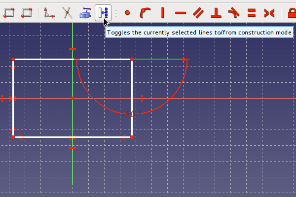
In the first part was shown, that helper constructions are not necessary for the triangle. But nevertheless the sketcher provides construction geometry, which is useful for more complex problems. Any line can be converted to a construction line with the button. The construction lines are shown in the sketch as blue lines. They can be used for constraints in the same way as other lines, but are not shown and not used when the sketch is closed.
Giving the task to make a rectangle with the side length having the golden ratio. Wikipedia shows how to construct two lines with a length ratio of the golden ratio.
The sketcher is a perfect tool to construct a rectangle with the golden ratio for the side length. The size of the rectangle can be later changed without making a new construction. The construction steps for the golden ratio according to Wikipedia are:
- Having a line segment AB, construct a perpendicular BC at point B, with BC half the length of AB. Draw the hypotenuse AC.
- Draw an arc with center C and radius BC. This arc intersects the hypotenuse AC at point D.
- Draw an arc with center A and radius AD. This arc intersects the original line segment AB at point S. Point S divides the original segment AB into line segments AS and SB with lengths in the golden ratio.
Here is a step by step explanation, how this can be done.
- Make a new sketch as explained at the triangle example.
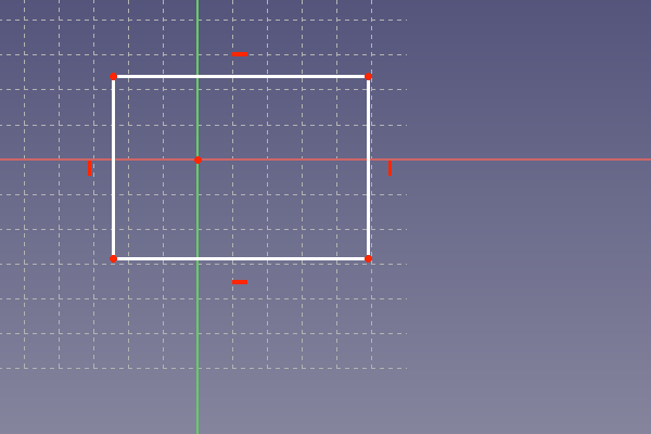
- Draw a rectangle in the sketch. Use the button File:Sketcher Rectangle.svg The following picture shows the rectangle. FreeCAD did add horizontal and vertical constraints to the rectangle. This rectangle can not be rotated.
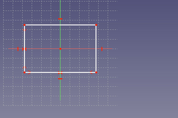
The rectangle should stay in the center of the coordinate system. To achieve this, a symmetry constraint is added to a horizontal line. This is done by selecting first the two vertices of the horizontal line and then the vertical axis of the coordinate system. The symmetry constraint is added by clicking on the button . The same is done for a vertical line, but instead now the horizontal axis is selected as symmetry axis. The picture below shows the result. The rectangle stays now at the center and can only be resized but not moved.
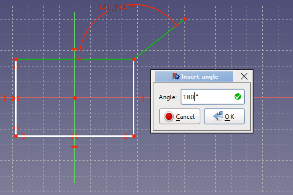
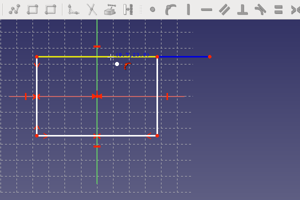
This was the preparation for the rectangle. The top horizontal line should be the distance AS of the golden ration construction. An additional line is needed to represent the SB-distance. It is drawn a little bit skewed as shown below. This avoids the auto-constraining to horizontal. This line should instead be constrained later with a 180°-angle, in order to avoid the existence of multiple solutions to the constructed constrain-combination. If the line is drawn with an horizontal constrained, the sketcher will complain later at adding the 180°-angle constrained. The horizontal constrained has to be removed in such a case. The picture shows how to add an angle-constraint by selecting two lines and clicking at . After adding a line, it is often advisable to drag at the line with the mouse. This will easily show, if a line is not attached to the other drawn elements. If a line is not connected right to the other lines, problems may arise in later steps of the part construction.
The last line is not part of the rectangle. It is therefore necessary to convert it into a construction line. Selecting the line and clicking at the button does the conversion.
The line has now a blue color as visible below. The recipe from Wikipedia for the golden ratio requires a line half of the distance AB. In order to get a reference point for this, an additional vertex is set at the line with the tool. This is shown below.
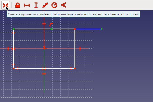
The reference point should stay at the center of the distance AB. This will be achieved by selecting first the two endpoints of the distance AB and third selecting the center point. When all three points are selected in the right sequence, the symmetry constraint can be set at clicking at the button, as shown below.
The Picture below shows already the second side BC of the construction triangle. This line was drawn as described above and converted to a construction line. This line must have a vertical constraint as visible in the picture. This can be easily achieved by drawing the line nearly vertical. If the line is nearly vertical a vertical constraint symbol is shown and set by the Sketcher when finishing the line at this state.
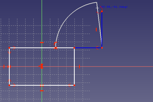
The line BC must have half of the length of AB. There is only a reference point available for this purpose, so the equality constraint can not be used. The equality constraint would need a line with this length as reference, which is not available in the construction. Therefore the classical arc is used to define the length BC. The picture below shows the drawing of the arc. The arc-tool [[Image:|24px]] is used. First the center point is set at B. The point should be visible beneath the arc-tool at clicking at B. Often the arc-tool has not has to be not directly over the target point but a little beneath, in order to get the coincidence point visible. Second the radius of the arc is defined by setting the next point at the reference point. The last point of the arc is set in the neighborhood of the point C. It is important, that the first two points are fixed to C and the center point. This should be tested with dragging at the arc after finishing it.
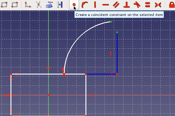
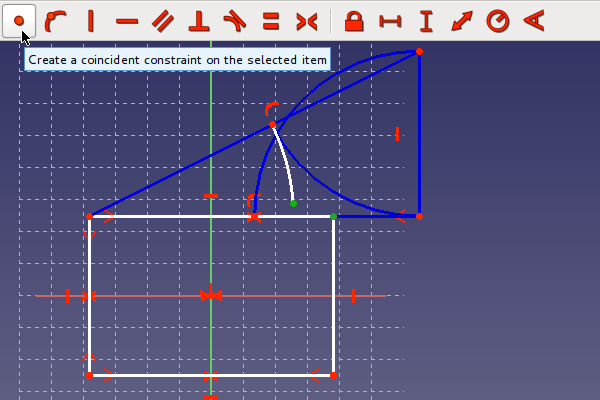
In order to define the length of BC, the line must end at the arc. This will be done by setting a coincidence constraint between the last arc point and the C point as shown below. Both points have to be selected and the create a coincidence button has to be clicked.
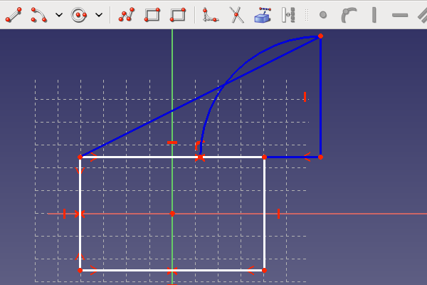
The next picture shows the ready triangle. The hypotenuse AC is already drawn and converted to a construction line.
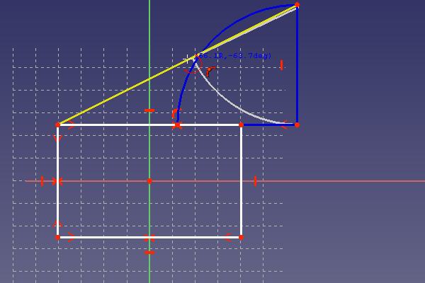
Now step 2 of the Wikipedia recipe has to be constructed. A second arc has to be drawn with the center point at C and the starting point at B. The last point should be end at the hypotenuse as shown in the picture below.
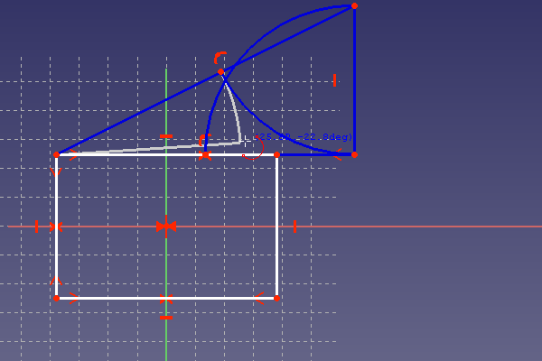
The drawn arc was converted to a construction line. Now step 3 of the Wikipedia recipe starts with drawing the last arc as shown in the picture below. The radius of this arc has to be defined with the above constructed point on the hypotenuse. The last point will usually not end at a corner of the rectangle. But this is not a problem, as it will be fixed later. The last point may set as shown below.
Now the final step has to be made, in order to made the horizontal line of the rectangle equal to the distance AS. This is shown below by setting a coincidence constraint between the end of the last arc and the corner of the rectangle.
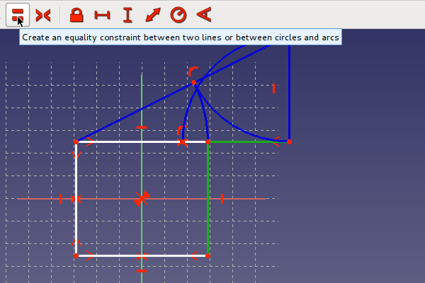
Now the vertical line has to be made the length of the distance SC. Setting an equality constraint by selecting the button as shown below, will do this.
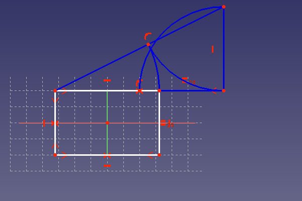
The next picture shows the rectangle with a side length ratio equal to the golden ratio. The rectangle should have only left one degree of freedom. So at dragging at it, it should only change its size but not move. If a certain size of one side is needed, a length constraint can be added to this side. Other wise the sketch is ready and can be closed. Only a rectangle should than be visible in the FreeCAD window.
Exercise: resilient sketch
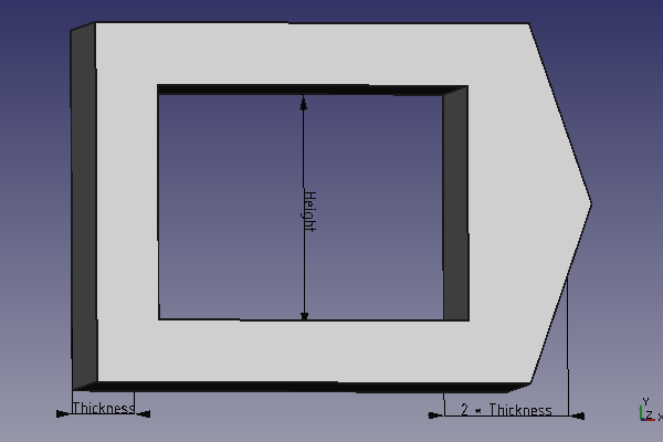
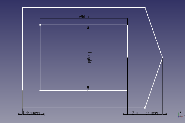
The above example introduced construction lines. Now some important things to make resilient sketches are discussed. Here is an exercise to get some practice at working with the sketcher. The goal is to make a sketch for something like a special frame as shown below.
There should be only three dimensions needed to define the frame. In order to make changing dimensions easier, the constraints can be renamed to something memorable. Just select the constraint in the list view and press <F2>. The constraint can be named for example to "Thickness". The drawing below shows the dimensions. The peak at the right side should have two times the wall thickness.
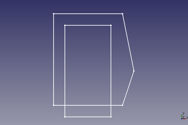
The sketch should look as intended also after changing the key dimensions for example to 2000 mm and back to 30. You may need to use angle constraints at certain places to reach this goal. The picture below shows a sketch, which was not robust against such changes. It is unusable now. In order to get the original state back, the undo-button can be used.
The above sketch is unusable for the Part-Design Workbench. Only Profile without intersecting lines are allowed. Construction lines may intersect. Those are not used for making solids.
One of the main usage of the Sketcher is the construction of parts in the Part-Design-workbench. The already existing geometry can be used similar to construction lines. As this tutorial takes its focus more on the basic sketcher functionality, have a look here for usage of external geometry: Sketcher External
