Sketcher ConstrainAngle/fr: Difference between revisions
m (minor) |
(Updating to match new version of source page) |
||
| Line 1: | Line 1: | ||
| ⚫ | |||
=Constraint_InternalAngle/fr= |
|||
| ⚫ | {{GuiCommand |
||
==Description== |
====Description==== |
||
This tool constrains the angle between two selected lines in a sketch to be a specified value. By default, the internal angle, the smaller of the angles formed at the intersection of two lines (or their extensions) is constrained.<br /> |
|||
If a single line is selected, the angle is constrained relative to the horizontal axis of the selected sketcher plane |
|||
====Operation==== |
|||
Cet outil contraint à une valeur spécifiée, l'angle entre deux lignes sélectionnées dans une esquisse.<br> |
|||
Select any two lines in the sketch by clicking on them in sequence. They will change colour to dark green when selected. The direction of the line form the first point created to the end point is significant in calculation of the angle between the lines.<br /><br /> |
|||
Par défaut, le plus petit des angles interne, formés par l'intersection de deux lignes (ou de leurs prolongements) est contraint. |
|||
[[File:ConstrainAngle1.png|256px|<span title="Selected lines"></span>]]<br /><br /> |
|||
Si une seule ligne est sélectionnée, l'angle est contraint par rapport à l'axe horizontal du plan de l'esquisse. |
|||
Then click on the ConstraintAngle icon([[Image:Constraint_InternalAngle.png|16px]]) in the Sketcher or Part Design toolbar or select the ConstrainAngle menu item from the Sketcher constraints sub menu of either the Sketcher (Sketcher workbench) or Part Design (Part Design workbench)menu item to add the constraint. <br /><br /> |
|||
The constraint is initially set to the current internal angle between the lines and the Constraint is added to the Tasks tab in the Combo View panel. <br /><br /> |
|||
[[File:ConstrainAngle2.png|256px|<span title="Constraint applied"></span>]]<br /><br /> |
|||
Doubleclicking on the Constraint in the Tasks tab will bring up a pop-up dialog box in which this value may be edited to set it to a desired value. Alternatively, the datum text in the 3D view may be double clicked to bring up the pop-up dialog to set the value.<br /><br /> |
|||
[[File:ConstrainAngle3.png|256px|<span title="Editing value"></span>]]<br /><br /> |
|||
[[File:ConstrainAngle4.png|256px|<span title="Constraint applied"></span>]]<br /><br /> |
|||
The value can be set to values greater than 180 (or even 360), in which case it becomes a constraint on the external angle and the angle is interpreted as modulo 360 degrees.<br /><br /> |
|||
The absolute mode is invoked by only selecting one line before applying the constraint.<br /><br /> |
|||
[[File:ConstrainAngle5.png|256px|<span title="Constraint applied"></span>]]<br /><br /> |
|||
Applying the constraint, the angle is constrained relative to the horizontal axis of the selected sketch plane.<br /><br /> |
|||
[[File:ConstrainAngle6.png|256px|<span title="Constraint applied"></span>]]<br /><br /> |
|||
Selecting the second line which was drawn from the upper right to lower left.<br /><br /> |
|||
[[File:ConstrainAngle7.png|256px|<span title="Constraint applied"></span>]]<br /><br /> |
|||
And applying the constraint as before,<br /><br /> |
|||
[[File:ConstrainAngle8.png|256px|<span title="Constraint applied"></span>]]<br /><br /> |
|||
the line is now constrained to have a value relative to the direction of the horizontal axis in the clockwise direction (angle values are restricted to 180 degrees anticlockwise or clockwise).<br /><br /> |
|||
As before by double clicking on the constraint in either the Tasks tab of the Combo view or on the constraint in the 3D view will allow editing of the value of the constrained angle. |
|||
<languages/> |
|||
== Opérations == |
|||
Sélectionnez les deux lignes de l'esquisse en cliquant sur eux dans l'ordre.<br>En cliquant sur la ligne, elle devient vert foncée.<br>(La couleur est modifiable par '''Edition → Préférences → Affichage → Couleurs → Sélection''').<br>La direction de la ligne, du premier point créé vers le point final, est significatif pour le calcul de l'angle formé entre les deux lignes. |
|||
<center> |
|||
<gallery widths="600" heights="400"> |
|||
File:ConstrainAngle1.png|Ensuite, cliquez sur l'icône [[Image:Constraint_InternalAngle.png|16px]] dans la barre d'outils, ou la '''Sketcher''' ou sélectionnez l'élément de menu à partir de '''Sketch → Contraintes d'esquisse → Contrainte Angulaire''' soit du '''Sketcher (Sketcher workbench)''' ou Part Design (Part Design workbench) pour ajouter la contrainte.<br>La contrainte est fixée à l'angle interne entre les lignes sélectionnées, et, la contrainte est ajoutée à l'onglet '''Tâches''' dans la fenêtre '''Vue combinée'''. |
|||
</gallery> |
|||
</center> |
|||
<br> |
|||
<center> |
|||
<gallery widths="600" heights="400"> |
|||
File:ConstrainAngle2.png|Double-cliquer sur la contrainte dans l'onglet '''Tâches''' (fenêtre '''Vue combinée''') pour faire apparaître une boîte de dialogue pop-up dans laquelle cette valeur peut être éditéé à la valeur désirée. |
|||
</gallery> |
|||
</center> |
|||
<br> |
|||
<center> |
|||
<gallery widths="600" heights="400"> |
|||
File:ConstrainAngle3.png|Sinon, le texte de référence dans la vue 3D peut être double-cliqué pour faire apparaître la boîte de dialogue pour éditer la valeur. |
|||
</gallery> |
|||
</center> |
|||
<br> |
|||
<center> |
|||
<gallery widths="600" heights="400"> |
|||
File:ConstrainAngle4.png|La valeur peut être réglée à une valeur supérieure à 180° (ou même 360°), dans ce cas, il devient une contrainte sur l'angle et l'angle externe est interprété comme modulo 360°.<br>Le mode absolu est invoqué uniquement sur une ligne sélectionnée, avant d'appliquer la contrainte. |
|||
</gallery> |
|||
</center> |
|||
<br> |
|||
<center> |
|||
<gallery widths="600" heights="400"> |
|||
File:ConstrainAngle5.png|Pour appliquer la contrainte, l'angle est limité à l'axe horizontal du plan de l'esquisse sélectionnée. |
|||
</gallery> |
|||
</center> |
|||
<br> |
|||
<center> |
|||
<gallery widths="600" heights="400"> |
|||
File:ConstrainAngle6.png|La deuxième ligne a été sélectionnée à partir du haut à droite vers le bas à gauche. |
|||
</gallery> |
|||
</center> |
|||
<br> |
|||
<center> |
|||
<gallery widths="600" heights="400"> |
|||
File:ConstrainAngle7.png|Et maintenant, appliquons la contrainte comme précédemment. |
|||
</gallery> |
|||
</center> |
|||
<br> |
|||
<center> |
|||
<gallery widths="600" heights="400"> |
|||
File:ConstrainAngle8.png|La ligne est a présent contrainte avec une valeur relative à la direction de l'axe horizontal, dans le sens horaire (valeurs des angles sont '''limités à 180 degrés''' dans le sens horaire ou inverse).<br>Comme précédemment, en double-cliquant sur la contrainte dans un des deux modes, sous l'onglet '''Tâches''' de la fenêtre '''Vue combinée''', ou sur la contrainte dans la vue 3D, permet l'édition de la valeur de l'angle à contraindre. |
|||
</gallery> |
|||
</center> |
|||
<br> |
|||
{{clear}} |
|||
{{LesOutilsContraintesDEsquisse}} |
|||
<br> |
|||
{{languages/fr | {{en|Constraint_InternalAngle}} {{es|Constraint_InternalAngle/es}} {{it|Constraint_InternalAngle/it}} }} |
|||
Revision as of 22:36, 21 December 2013
|
|
| Menu location |
|---|
| Sketch → Sketcher constraints → Constrain angle |
| Workbenches |
| Sketcher, PartDesign |
| Default shortcut |
| A |
| Introduced in version |
| - |
| See also |
| Constraint Length, Constraint Perpendicular |
Description
This tool constrains the angle between two selected lines in a sketch to be a specified value. By default, the internal angle, the smaller of the angles formed at the intersection of two lines (or their extensions) is constrained.
If a single line is selected, the angle is constrained relative to the horizontal axis of the selected sketcher plane
Operation
Select any two lines in the sketch by clicking on them in sequence. They will change colour to dark green when selected. The direction of the line form the first point created to the end point is significant in calculation of the angle between the lines.

Then click on the ConstraintAngle icon(![]() ) in the Sketcher or Part Design toolbar or select the ConstrainAngle menu item from the Sketcher constraints sub menu of either the Sketcher (Sketcher workbench) or Part Design (Part Design workbench)menu item to add the constraint.
) in the Sketcher or Part Design toolbar or select the ConstrainAngle menu item from the Sketcher constraints sub menu of either the Sketcher (Sketcher workbench) or Part Design (Part Design workbench)menu item to add the constraint.
The constraint is initially set to the current internal angle between the lines and the Constraint is added to the Tasks tab in the Combo View panel.

Doubleclicking on the Constraint in the Tasks tab will bring up a pop-up dialog box in which this value may be edited to set it to a desired value. Alternatively, the datum text in the 3D view may be double clicked to bring up the pop-up dialog to set the value.


The value can be set to values greater than 180 (or even 360), in which case it becomes a constraint on the external angle and the angle is interpreted as modulo 360 degrees.
The absolute mode is invoked by only selecting one line before applying the constraint.

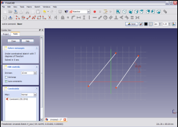
Applying the constraint, the angle is constrained relative to the horizontal axis of the selected sketch plane.

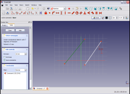
Selecting the second line which was drawn from the upper right to lower left.

And applying the constraint as before,

the line is now constrained to have a value relative to the direction of the horizontal axis in the clockwise direction (angle values are restricted to 180 degrees anticlockwise or clockwise).
As before by double clicking on the constraint in either the Tasks tab of the Combo view or on the constraint in the 3D view will allow editing of the value of the constrained angle.