SheetMetal AddCornerRelief: Difference between revisions
m (→Differnt shapes: fix typo in header) |
(Marked this version for translation) |
||
| (12 intermediate revisions by the same user not shown) | |||
| Line 24: | Line 24: | ||
<!--T:4--> |
<!--T:4--> |
||
The [[Image:SheetMetal_AddCornerRelief.svg|24px]] '''SheetMetal AddCornerRelief''' command adds a corner relief |
The [[Image:SheetMetal_AddCornerRelief.svg|24px]] '''SheetMetal AddCornerRelief''' command adds a corner relief. A relief is usually created at corners where two bends meet, but the command can also create a relief at an open corner. |
||
<!--T:17--> |
|||
| ⚫ | |||
</translate> |
</translate> |
||
| Line 30: | Line 33: | ||
[[Image:SheetMetal_AddCornerRelief-02.png|300px]] |
[[Image:SheetMetal_AddCornerRelief-02.png|300px]] |
||
<translate> |
<translate> |
||
<!--T:18--> |
|||
{{Caption|Default corner of two bends |
{{Caption|Default corner of two bends → Corner with added corner relief}} |
||
The command can as well be used to add a relief to an open corner at one end of a bend. |
|||
</translate> |
</translate> |
||
| Line 39: | Line 40: | ||
[[Image:SheetMetal_AddCornerRelief-04.png|300px]] |
[[Image:SheetMetal_AddCornerRelief-04.png|300px]] |
||
<translate> |
<translate> |
||
<!--T:19--> |
|||
{{Caption|Default open corner |
{{Caption|Default open corner → Open corner with added corner relief}} |
||
| ⚫ | |||
== Usage == <!--T:5--> |
== Usage == <!--T:5--> |
||
<!--T:20--> |
|||
# Select two edges of a corner. |
# Select two edges of a corner. |
||
# Activate the [[Image:SheetMetal_AddCornerRelief.svg|16px]] '''SheetMetal AddCornerRelief''' command using one of the following: |
# Activate the [[Image:SheetMetal_AddCornerRelief.svg|16px]] '''SheetMetal AddCornerRelief''' command using one of the following: |
||
#* The {{Button|[[Image:SheetMetal_AddCornerRelief.svg|16px]] [[SheetMetal_AddCornerRelief|Add Corner Relief]]}} button. |
#* The {{Button|[[Image:SheetMetal_AddCornerRelief.svg|16px]] [[SheetMetal_AddCornerRelief|Add Corner Relief]]}} button. |
||
#* The {{MenuCommand|SheetMetal → [[Image:SheetMetal_AddCornerRelief.svg|16px]] Add Corner Relief}} menu option. |
#* The {{MenuCommand|SheetMetal → [[Image:SheetMetal_AddCornerRelief.svg|16px]] Add Corner Relief}} menu option. |
||
#* The keyboard shortcut: {{KEY|C}} then {{KEY|R}} |
#* The keyboard shortcut: {{KEY|C}} then {{KEY|R}}. |
||
== |
== Relief shapes == <!--T:21--> |
||
<!--T:22--> |
|||
The |
The shape of a corner relief can be altered by changing its property values: |
||
<!--T:23--> |
|||
The value of the property {{PropertyData|ReliefSketch}} can be chosen from a list: {{value|Circle}} (default), {{value|Circle-Scaled}}, {{value|Square}}, {{value|Square-Scaled}}, {{value|Sketch}}. |
The value of the property {{PropertyData|ReliefSketch}} can be chosen from a list: {{value|Circle}} (default), {{value|Circle-Scaled}}, {{value|Square}}, {{value|Square-Scaled}}, {{value|Sketch}}. |
||
* {{value|Circle}} and {{value|Square}} use the value of the property {{PropertyData|Size}} to scale the relief. |
|||
* {{value|Circle-Scaled}} and {{value|Square-Scaled}} use the value of the property {{PropertyData|Size Ratio}} to scale the relief. |
|||
* {{value|Sketch}} activates the use of the sketch listed in the property {{PropertyData|Sketch}} to define the relief shape. |
|||
</translate> |
</translate> |
||
| Line 67: | Line 68: | ||
[[Image:SheetMetal_AddCornerRelief-07.png|200px]] |
[[Image:SheetMetal_AddCornerRelief-07.png|200px]] |
||
<translate> |
<translate> |
||
<!--T:24--> |
|||
| ⚫ | |||
| ⚫ | |||
| ⚫ | |||
==Notes== |
|||
| ⚫ | |||
| ⚫ | |||
<div class="mw-collapsible mw-collapsed"> |
|||
| ⚫ | |||
<div class="mw-collapsible-content"> |
|||
<!--T:26--> |
|||
To get an idea how and where the relief is placed we unfold a default corner without a relief. |
To get an idea how and where the relief is placed we unfold a default corner without a relief. |
||
| Line 87: | Line 82: | ||
<translate> |
<translate> |
||
<!--T:27--> |
|||
{{Caption|Default corner of two bends |
{{Caption|Default corner of two bends → Corner with unfold solid → Corner in top view}} |
||
<!--T:28--> |
|||
The next step is to open the unfold sketch, |
The next step is to open the unfold sketch, create a circle through 3 points and add a radius dimension.<br/> Now we add a corner relief, create the corresponding unfold solid and open the first unfold sketch again.<br/> Adding a concentric circle of 3 mm radius reveals that we have found out how the internal circle is positioned as the new circle fits perfectly into the cut-out of the relief's unfold solid. |
||
</translate> |
</translate> |
||
| Line 96: | Line 93: | ||
<translate> |
<translate> |
||
<!--T:29--> |
|||
{{Caption|Default corner with unfold sketch |
{{Caption|Default corner with unfold sketch → Corner with default relief and the same unfold sketch}} |
||
<!--T:30--> |
|||
Trying to set the property {{PropertyData|Size}} to a value below the determined 1,67 mm will result in an error; any value above should work fine. |
Trying to set the property {{PropertyData|Size}} to a value below the determined 1,67 mm will result in an error; any value above should work fine. |
||
<!--T:31--> |
|||
Switching to Circle-Scaled and creating another unfold solid shows that 1,67 mm is the base for the property {{PropertyData|Size Ratio}}, too. |
Switching to Circle-Scaled and creating another unfold solid shows that 1,67 mm is the base for the property {{PropertyData|Size Ratio}}, too. |
||
== Notes == <!--T:32--> |
|||
</div> <!-- End of collapsible element for content section. Do not remove! --> |
|||
</div> <!-- End of collapsible element for ... section. Do not remove! --> |
|||
<!--T:33--> |
|||
| ⚫ | |||
| ⚫ | |||
== Properties == <!--T:6--> |
== Properties == <!--T:6--> |
||
| Line 111: | Line 114: | ||
<!--T:9--> |
<!--T:9--> |
||
A SheetMetal CornerRelief object is derived from a [[Part_Feature|Part Feature]] object and inherits all its properties. It also has the following additional properties |
A SheetMetal CornerRelief object is derived from a [[Part_Feature|Part Feature]] object and inherits all its properties. It also has the following additional properties: |
||
=== Data === <!--T:10--> |
=== Data === <!--T:10--> |
||
| Line 119: | Line 122: | ||
<!--T:12--> |
<!--T:12--> |
||
* {{PropertyData|Label|String}}: Default value: {{value|CornerRelief}} (+ a sequential number for second and following items). </br>The user editable name of this object, it may be any arbitrary UTF8 string. |
|||
* {{PropertyData|Base Feature|Link|hidden}}: Base Feature. Link to the parent feature. |
* {{PropertyData|Base Feature|Link|hidden}}: Base Feature. Link to the parent feature. |
||
* {{PropertyData|_Body|LinkHidden|hidden}}: Hidden link to the parent body. |
* {{PropertyData|_Body|LinkHidden|hidden}}: Hidden link to the parent body. |
||
Latest revision as of 08:34, 12 May 2022
This documentation is not finished. Please help and contribute documentation.
GuiCommand model explains how commands should be documented. Browse Category:UnfinishedDocu to see more incomplete pages like this one. See Category:Command Reference for all commands.
See WikiPages to learn about editing the wiki pages, and go to Help FreeCAD to learn about other ways in which you can contribute.
|
|
| Menu location |
|---|
| SheetMetal → Add Corner Relief |
| Workbenches |
| SheetMetal |
| Default shortcut |
| C R |
| Introduced in version |
| - |
| See also |
| None |
Description
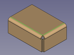
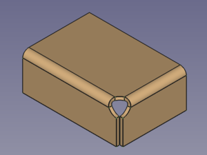
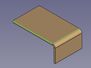
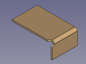
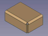
The SheetMetal AddCornerRelief command adds a corner relief. A relief is usually created at corners where two bends meet, but the command can also create a relief at an open corner.
The command can only create one relief at a time.
Default corner of two bends → Corner with added corner relief
Default open corner → Open corner with added corner relief
Usage
- Select two edges of a corner.
- Activate the
SheetMetal AddCornerRelief command using one of the following:
- The
Add Corner Relief button.
- The SheetMetal →
Add Corner Relief menu option.
- The keyboard shortcut: C then R.
- The
Relief shapes
The shape of a corner relief can be altered by changing its property values:
The value of the property DataReliefSketch can be chosen from a list: Circle (default), Circle-Scaled, Square, Square-Scaled, Sketch.
CircleandSquareuse the value of the property DataSize to scale the relief.Circle-ScaledandSquare-Scaleduse the value of the property DataSize Ratio to scale the relief.Sketchactivates the use of the sketch listed in the property DataSketch to define the relief shape.
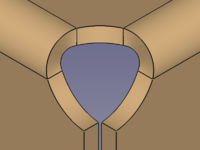
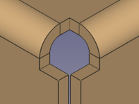
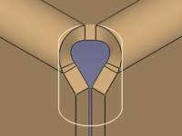
Circular relief (default settings) → Square relief (default settings) → Sketch based relief
A closer look at relief sizes
To get an idea how and where the relief is placed we unfold a default corner without a relief.
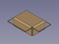
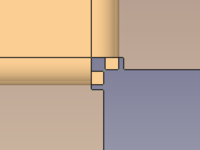
Default corner of two bends → Corner with unfold solid → Corner in top view
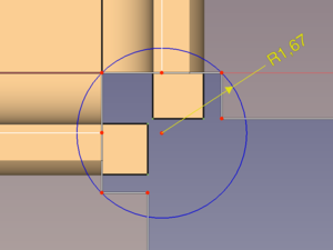
The next step is to open the unfold sketch, create a circle through 3 points and add a radius dimension.
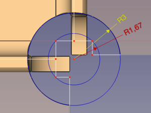
Now we add a corner relief, create the corresponding unfold solid and open the first unfold sketch again.
Adding a concentric circle of 3 mm radius reveals that we have found out how the internal circle is positioned as the new circle fits perfectly into the cut-out of the relief's unfold solid.
Default corner with unfold sketch → Corner with default relief and the same unfold sketch
Trying to set the property DataSize to a value below the determined 1,67 mm will result in an error; any value above should work fine.
Switching to Circle-Scaled and creating another unfold solid shows that 1,67 mm is the base for the property DataSize Ratio, too.
Notes
- The k factor defines where within the thickness of a sheet the neutral axis is located.
- (It would be nice to know if this factor is according to ISO or ANSI standard...)
Properties
See also: Property editor.
A SheetMetal CornerRelief object is derived from a Part Feature object and inherits all its properties. It also has the following additional properties:
Data
Base
- Data (hidden)Base Feature (
Link): Base Feature. Link to the parent feature. - Data (hidden)_Body (
LinkHidden): Hidden link to the parent body.
Parameters
- DataReliefSketch (
Enumeration): "Corner Relief Type".Circle(default),Circle-Scaled,Square,Square-Scaled,Sketch. - DataSize (
Length): "Size of Shape". Default:3,00 mm. - DataSize Ratio (
Float): "Size Ratio of Shape". Default:1,50. - Database Object (
LinkSub): "Base Object". Links to the pair of edges defining the Corner Relief position. - Datakfactor (
FloatConstraint): "Neutral Axis Position". Default:0,50.
Parameters1
- DataSketch (
Link): "Corner Relief Sketch". - DataXOffset (
Distance): "Gap from side one". Default:0,00 mm. - DataYOffset (
Distance): "Gap from side two". Default:0,00 mm.
