Scripts: Difference between revisions
(Some more work on translation) |
(more traslated effort added some tag at the bottom) |
||
| Line 91: | Line 91: | ||
return obj_b |
return obj_b |
||
# object definitions |
|||
obj = cubo("test_cube", 5, 5, 5) |
obj = cubo("test_cube", 5, 5, 5) |
||
| Line 123: | Line 125: | ||
Even here |
Even here nothing too exciting. But please note some peculiarities: |
||
* The absence of the usual reference to the {{incode|App.}}, present in many Documentation code snippets, is deliberate, this code could be used even invoking FreeCAD as a module in an external Python, the thing is not easily doable with an AppImage, but with some care it could be done. Plus in the standard Python motto that "better explicit than implicit" {{incode|App.}} is explaining in a very "poor" way where the things are from. |
* The absence of the usual reference to the {{incode|App.}}, present in many Documentation code snippets, is deliberate, this code could be used even invoking FreeCAD as a module in an external Python, the thing is not easily doable with an AppImage, but with some care it could be done. Plus in the standard Python motto that "better explicit than implicit" {{incode|App.}} is explaining in a very "poor" way where the things are from. |
||
* note the use of the "constant" name assigned to the active Document in {{incode|DOC}} = {{incode|FreeCAD.activeDocument()}}; active Document is not a "constant" in a strict sense, but in a "semantical" way is our "active Document", that for our use is a proper "constant" so the Python convention to use the "ALL CAPS" name for "constants", not to mention that {{incode|DOC}} is much shorten than {{incode|FreeCAD.activeDocument()}}. |
* note the use of the "constant" name assigned to the active Document in {{incode|DOC}} = {{incode|FreeCAD.activeDocument()}}; active Document is not a "constant" in a strict sense, but in a "semantical" way is our "active Document", that for our use is a proper "constant" so the Python convention to use the "ALL CAPS" name for "constants", not to mention that {{incode|DOC}} is much shorten than {{incode|FreeCAD.activeDocument()}}. |
||
* every method returns a geometry, this became clear in the continuation of the page. |
* every method returns a geometry, this became clear in the continuation of the page. |
||
* geometry didn't have the {{incode|Placement}} property, when |
* geometry didn't have the {{incode|Placement}} property, when using the simple geometries to make more complex geometry, managing {{incode|Placement}} is a ankward thing. |
||
Now what to do with this geometries? |
|||
Let's introduce boolean opearations. As a starter example put these lines after {{incode|base_cyl(...}}, this create a method for a '''Fusion''' also know as '''Union''' operation: |
|||
Ora dobbiamo pur farci qualcosa con questi oggetti, quindi introduciamo le operazioni booleane. Un esempio di metodo che compie un'operazione di '''Unione''' è questo: |
|||
{{Code|code= |
{{Code|code= |
||
| Line 144: | Line 148: | ||
Nothing exceptional also here, note however the uniformity of the methd building; This approach is more linear that those seen around other tutorial on scripting, this "linearity" help greatly in readability and also with cut-copy-paste operations. |
|||
anche qui nulla di eccezionale, notate però l'uso di molta uniformità nel codice, aiuta molto quando si vuole fare copia e incolla nella creazioni complesse. |
|||
Modify the line below the method after the section {{incode|# object definition}} |
|||
Inseriamo dopo il metodo {{incode|base_cyl}} le righe sopra e modifichiamo quelle sotto in modo da leggere: |
|||
{{Code|code= |
{{Code|code= |
||
# object definitions |
|||
# definizione oggetti |
|||
obj = cubo("cubo_di_prova", 5, 5, 5) |
obj = cubo("cubo_di_prova", 5, 5, 5) |
||
| Line 281: | Line 285: | ||
'''Alla prossima!''' |
'''Alla prossima!''' |
||
<nowiki>{{Tutorials navi}}</nowiki> |
|||
Revision as of 14:48, 3 March 2020
Editing Scripts
Work in progress, the page was written by error in Italian, now I'm trying to translate it in English, sorry for the inconvenience
With Scripting we mean create topological objects using FreeCAD Python interpreter. FreeCAD could be used a "very good" replacement of OpenSCAD, manìinly beacause it has a real Python interpreter, that means that it has a real programming language on board, almost everything you could do with the GUI, is doable with a Python Script.
Sadly information about scripting in the documentation, and even in this wiki are scattered around and lacks of "writing" uniformity and most of them are explained in a too technical manner.
Wetting you appetite
The first obstacle in an easy way to scripting is that there is no direct way to access the FreeCAD internal Python editor through a menu item or a icon on the toolbar area, but knowing that FreeCAD opens a file with a .py extension in the internal Python editor, the most simple trick is create in your favourite text editor and then open it with the usual command File - Open.
To make the things in a polite way, the fila has to be written with some order, FreeCAD Python editor have a good "Syntax HIghlighting" that lacks in many simple editors like Windows Notepad or some basic Linux editors, so it is sufficient to write these few lines:
"""script.py

   Primo script per FreeCAD

"""
Save them with a meaningfull name with .py extension and load the resulting file in FreeCAD, with the said File - Open command.
A minimal example of what is necessary to have in a script is shown in this portion of code that you could be use as a template for almost any future script:
"""filename.py

   Here a short but significant description of what the script do

"""

import FreeCAD
from FreeCAD import Base, Vector
import Part
from math import pi, sin, cos

DOC = FreeCAD.activeDocument()
DOC_NAME = "Pippo"

def clear_doc():
    """
    Clear the active document deleting all the objects
    """
    for obj in DOC.Objects:
        DOC.removeObject(obj.Name)

def setview():
    """Rearrange View"""
    FreeCAD.Gui.SendMsgToActiveView("ViewFit")
    FreeCAD.Gui.activeDocument().activeView().viewAxometric()


if DOC is None:
    FreeCAD.newDocument(DOC_NAME)
    FreeCAD.setActiveDocument(DOC_NAME)
    DOC = FreeCAD.activeDocument()

else:

    clear_doc()

# EPS= tolerance to use to cut the parts
EPS = 0.10
EPS_C = EPS * -0.5
Some tricks are incorporated in the above code:
import FreeCADThis line import FreeCAD in the FreeCAD Python interpreter, it may seem a redundant thing, but it isn'tfrom FreeCAD import Base, VectorBase and Vector are widely used in FreeCAD scipting, import them in this manner will save you to invoke them withFreeCAD.VectororFreeCAD.Baseinstead ofBaseorVector, this will save many keystrokes and make codelines much smaller.
Let's start with a small script that does a very small job, but display the power of this approach.
def cubo(nome, lung, larg, alt):
    obj_b = DOC.addObject("Part::Box", nome)
    obj_b.Length = lung
    obj_b.Width = larg
    obj_b.Height = alt

    DOC.recompute()

    return obj_b

# object definitions

obj = cubo("test_cube", 5, 5, 5)

setview()
Put these lines after the "template" code and press the green arrow in the Macro toolbar
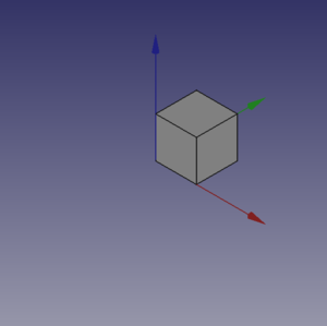
You will see some magic things, a new document is open named "Pippo" (Italian name of Goofy) and you will see in the 3d view a cube, like the one in the image below.
Something more...
Not too amazing? Yes, but we have to start somewhere, same thing we can do with a Cylinder, add these lines of code after the cubo( method and before the line {{{1}}}.
def base_cyl(nome, ang, rad, alt ):
    obj = DOC.addObject("Part::Cylinder", nome)
    obj.Angle = ang
    obj.Radius = rad
    obj.Height = alt

    DOC.recompute()

    return obj
Even here nothing too exciting. But please note some peculiarities:
- The absence of the usual reference to the
App., present in many Documentation code snippets, is deliberate, this code could be used even invoking FreeCAD as a module in an external Python, the thing is not easily doable with an AppImage, but with some care it could be done. Plus in the standard Python motto that "better explicit than implicit"App.is explaining in a very "poor" way where the things are from. - note the use of the "constant" name assigned to the active Document in
DOC=FreeCAD.activeDocument(); active Document is not a "constant" in a strict sense, but in a "semantical" way is our "active Document", that for our use is a proper "constant" so the Python convention to use the "ALL CAPS" name for "constants", not to mention thatDOCis much shorten thanFreeCAD.activeDocument(). - every method returns a geometry, this became clear in the continuation of the page.
- geometry didn't have the
Placementproperty, when using the simple geometries to make more complex geometry, managingPlacementis a ankward thing.
Now what to do with this geometries?
Let's introduce boolean opearations. As a starter example put these lines after base_cyl(..., this create a method for a Fusion also know as Union operation:
def fuse_obj(nome, obj_0, obj_1):
    obj = DOC.addObject("Part::Fuse", nome)
    obj.Base = obj_0
    obj.Tool = obj_1
    obj.Refine = True
    DOC.recompute()

    return obj
Nothing exceptional also here, note however the uniformity of the methd building; This approach is more linear that those seen around other tutorial on scripting, this "linearity" help greatly in readability and also with cut-copy-paste operations.
Modify the line below the method after the section # object definition
# object definitions

obj = cubo("cubo_di_prova", 5, 5, 5)

obj1 = base_cyl('primo cilindro', 360,2,10)

fuse_obj("Fusione", obj, obj1)
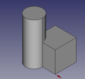
Lanciamo con il tasto freccia della barra strumenti macro e otteniamo:
Posizionamento
Il concetto è relativamente complesso, vedere il Tutorial aeroplano per una trattazione più sistematica.
Possiamo aver bisogno di posizionare una geometria in una posizione relativa ad un'altra geometria, cosa abbastanza frequente, il modo più comune è usare la proprietà Placement della geometria.
Ovviamente le possibilità su come specificare questa proprietà sono molte, alcune complesse da capire, questa scrittura della proprietà Placement, soprattutto per quanto riguarda la parte Rotation è in linea con quanto spiegato nel Tutorial citato e sembra la più gestibile.
FreeCAD.Placement(Vector(0,0,0), FreeCAD.Rotation(10,20,30), Vector(0,0,0))
Esiste sempre un punto di criticità, che è il punto di riferimento della costruzione, cioè il punto in base al quale è costruito l'oggetto, come descritto in questa tabella, copiata da Posizionamento:
| Geometria | Riferimento di Costruzione |
|---|---|
| Part::Box | vertice sinistro (minimo x), frontale (minimo y), in basso (minimo z) |
| Part::Sphere | centro della sfera (centro del suo contenitore cubico) |
| Part::Cylinder | centro della faccia di base |
| Part::Cone | centro della faccia di base (o superiore se il raggio della faccia di base vale 0) |
| Part::Torus | centro del toro |
| Caratteristiche derivate da Sketch | la caratteristica eredita la posizione dello schizzo sottostante. Lo schizzo inizia sempre con Position = (0,0,0). |
Queste informazioni sono da tenere ben presente quando volete applicare una rotazione.
Facciamo qualche esempio, cancellate tutte le righe dopo il metodo base_cyl ed inserite queste righe:
def sfera(nome, rad):
    obj = DOC.addObject("Part::Sphere", nome)
    obj.Radius = rad

    DOC.recompute()

    return obj


def mfuse_obj(nome, objs):
    obj = DOC.addObject("Part::MultiFuse", nome)
    obj.Shapes = objs
    obj.Refine = True
    DOC.recompute()

    return obj


def aeroplano():

    lung_fus = 30
    diam_fus = 5
    ap_alare = lung_fus * 1.75
    larg_ali = 7.5
    spess_ali = 1.5
    alt_imp = diam_fus * 3.0
    pos_ali = (lung_fus*0.70)
    off_ali = (pos_ali - (larg_ali * 0.5))

    obj1 = base_cyl('primo cilindro', 360, diam_fus, lung_fus)

    obj2 = cubo('ali', ap_alare, spess_ali, larg_ali, True, off_ali)

    obj3 = sfera("naso", diam_fus)
    obj3.Placement = FreeCAD.Placement(Vector(0,0,lung_fus), FreeCAD.Rotation(0,0,0), Vector(0,0,0))

    obj4 = cubo('impennaggio', spess_ali, alt_imp, larg_ali, False, 0)
    obj4.Placement = FreeCAD.Placement(Vector(0,alt_imp * -1,0), FreeCAD.Rotation(0,0,0), Vector(0,0,0))

    objs = (obj1, obj2, obj3, obj4)

    obj = mfuse_obj("Forma esempio", objs)
    obj.Placement = FreeCAD.Placement(Vector(0,0,0), FreeCAD.Rotation(0,0,0), Vector(0,0,0))
    obj.Placement = FreeCAD.Placement(Vector(0,0,0), FreeCAD.Rotation(0,0,-90), Vector(0,0,pos_ali))

    DOC.recompute()

    return obj


aeroplano()

setview()
Analizziamo il codice:
- Abbiamo definito un metodo per creare una sfera, abbiamo usato la definizione più semplice, definendo solo il raggio.
- Abbiamo introdotto una seconda forma per l'Unione quella multipla, niente di speciale, notate solo che alla proprietà
Shapesabbiamo passato una tupla - Abbiamo definito una forma complessa, in modo "parametrico", cioè definendo alcuni parametri e mettendo delle formule che calcolano in modo automatico molti dei valori da passare alla geometria finale.
- Abbiamo usato prima di ritornare l'oggetto un posizionamento usando la poprietà
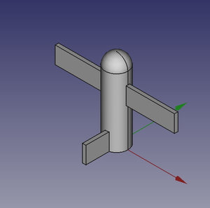
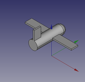
Rotatione il vettore finale del gruppo che definisce il centro di rotazione, secondo la scrittura Yaw-Pitch-Roll
 |
 |
 |
Potete facilmente notare che l'aereo ruota attorno al suo "baricentro" che ho fissato nel centro delle ali, in modo che la rotazione sia relativamente "naturale".
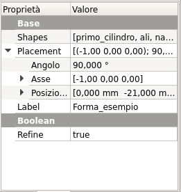
Notiamo però che se usiamo l'interfaccia grafica e visualizziamo la proprietà Placement abbiamo i dati che abbiamo inserito, questo significa che ogni modifica della proprietà modificherà il posizionamento della geometria, l'osservazione sarà importante nel proseguimento del discorso.
Alla prossima!
{{Tutorials navi}}