Part EditAttachment/de: Difference between revisions
HarryGeier (talk | contribs) (Created page with "Default, keine Referenz selektiert .") |
HarryGeier (talk | contribs) (Created page with "==== Normal zur Kante====") |
||
| Line 31: | Line 31: | ||
Default, keine Referenz selektiert . |
Default, keine Referenz selektiert . |
||
==== Normal |
==== Normal zur Kante==== |
||
Object is made perpendicular to edge. Optional vertex reference defines location . |
Object is made perpendicular to edge. Optional vertex reference defines location . |
||
Revision as of 08:59, 12 March 2018
Beschreibung
Attachment is ein Werkzeug um Objekte definiert aneinander zu befestigen. Das befestigte Objekt ist mit dem anderen Objekt so verbunden, das , wenn sich die Position des Ausgangsobjekts ändert, das befestigte Objekt mit bewegt wird.
Anwendung
- Wähle das Objekt, welches zu Befestigen ist.
- Wähle das Part → Attachment... Menü.
- Hinweis: Arbeitet man in PartDesign and und erstellt dort Skizzen, Bezugsgeometrie oder Primitivkörper, sind diese beiden Schritte nicht notwendig, die Parameterseite der Befestigungsmodi wird automatisch geöffnet.
- Under Attachment parameter steht , Nicht gebunden. . Die erste Schaltfläche zeigt Auswählen… , dies bedeutet, es wird eine Selektion im 3D Bildschirmbereich erwartet.
- Wähle nun eines der Grundelemente aus: Eckpunkt, Kante oder Fläche/Oberfläche. Bezugsgeometrie aus Part containers ist ebenfalls wählbar.
- Die erste Schaltfläche ändert ihre Beschriftung nun analog zum gewählten Element. im weissen Feld rechts, wird nun der Name des referenzierten Objekts und des Elements angezeigt. Wird z.b auf einem Quader (Box ) - Primitiv eine Oberfläche gewählt, zeigt das Feld Box:Face6.
- Wähle nun Befestigungsmodus aus der Liste. Die Liste der möglichen Modi passt sich an das gewählte Element an. Angehängt im Modus: wird nun unter der .. Parameter Überschrift angezeigt.
- Um währen der Auswahl Informationen über die Befestigungsmodi zu erahlten, bewegen Sie die Maus über die Liste der Modi und verweilen auf einer Zeile. Der Text erscheint in einem Infofenster ( Tooltip ).
- Bei Bedarf können nbis zu 4 weitere Elemente als Referenz gewählt werden, klicke dazu auf die Schaltfläche Referenz2, Referenz3, and Referenz4 unnd wiederhole Schritt 4.
- Zusätzlich kann eine Verschiebung Attachment Offset angegeben werden.
- Bestätige dann mit OK die Auswahlen.
Optionen
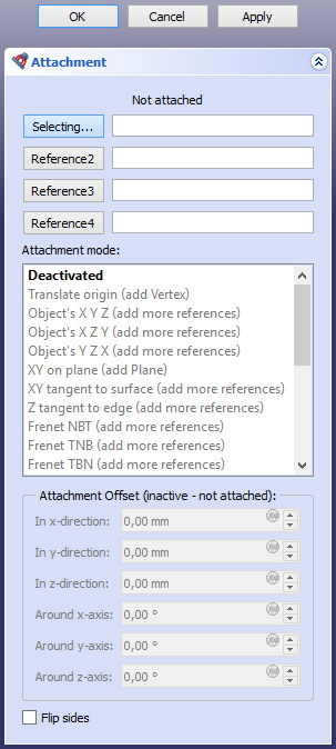
Befestigungs Modus
Deaktiviert
Default, keine Referenz selektiert .
Normal zur Kante
Object is made perpendicular to edge. Optional vertex reference defines location .
- Reference combinations
- Edge
- Edge, Vertex
- Vertex, Edge
Align O-N-X
Matches object's origin with first referenced vertex, then aligns its normal and horizontal plane axis toward vertex/along line .
- Reference combinations
- Vertex, Vertex, Vertex
- Vertex, Vertex, Edge
- Vertex, Edge, Vertex
- Vertex, Edge, Edge
- Vertex, Vertex
- Vertex, Edge
Align O-N-Y
Matches object's origin with first referenced vertex and aligns its normal and vertical plane axis toward vertex/along line .
- Reference combinations
- Vertex, Vertex, Vertex
- Vertex, Vertex, Edge
- Vertex, Edge, Vertex
- Vertex, Edge, Edge
- Vertex, Vertex
- Vertex, Edge
Align O-X-Y
Matches object's origin with first referenced vertex and aligns its horizontal and vertical plane axes toward vertex/along line .
- Reference combinations
- Vertex, Vertex, Vertex
- Vertex, Vertex, Edge
- Vertex, Edge, Vertex
- Vertex, Edge, Edge
- Vertex, Vertex
- Vertex, Edge
Align O-X-N
Matches object's origin with first referenced vertex and aligns its horizontal plane axis and normal toward vertex/along line .
- Reference combinations
- Vertex, Vertex, Vertex
- Vertex, Vertex, Edge
- Vertex, Edge, Vertex
- Vertex, Edge, Edge
- Vertex, Vertex
- Vertex, Edge
Align O-Y-N
Matches object's origin with first referenced vertex and aligns its vertical plane axis and normal toward vertex/along line .
- Reference combinations
- Vertex, Vertex, Vertex
- Vertex, Vertex, Edge
- Vertex, Edge, Vertex
- Vertex, Edge, Edge
- Vertex, Vertex
- Vertex, Edge
Align O-Y-X
Matches object's origin with first referenced vertex and aligns its vertical and horizontal plane axes toward vertex/along line .
- Reference combinations
- Vertex, Vertex, Vertex
- Vertex, Vertex, Edge
- Vertex, Edge, Vertex
- Vertex, Edge, Edge
- Vertex, Vertex
- Vertex, Edge
Translate origin
Object's origin is aligned to matched vertex. Orientation is controlled by Placement property.
- Reference combinations
- Vertex.
Object's XY
Plane is aligned to XY local plane of linked object .
- Reference combinations
- Any, Conic.
Object's XZ
Plane is aligned to XZ local plane of linked object .
- Reference combinations
- Any, Conic.
Object's YZ
Plane is aligned to YZ local plane of linked object .
- Reference combinations
- Any, Conic
Plane face
Plane is aligned to coincide to planar face .
- Reference combinations
- Plane
Tangent to surface
Plane is made tangent to surface at vertex .
- Reference combinations
- Face, Vertex
- Vertex, Face
Frenet NB
Plane is set to normal-binormal (NB) axes of Frenet-Serret coordinates at the point of the edge's curve that is closest to the vertex (or defined by MapPathParameter property, if vertex is not linked). The object's origin is translated to the vertex if the vertex is first, or kept at the curve if edge is first. This mode is similar to Normal to edge, except that X axis is well-defined.
Frenet TN
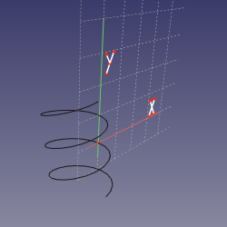
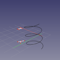
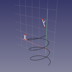
Plane is set to tangent-normal (TN) axes of Frenet-Serret coordinates at the point of the edge's curve that is closest to the vertex (or defined by MapPathParameter property, if vertex is not linked). The origin of sketch is translated to the vertex if the vertex is first, or kept at the curve if edge is first. Effectively, if the curve is planar, the sketching plane is the plane of the curve.
Frenet TB
Plane is set tangent-binormal (TB) axes of Frenet-Serret coordinates at the point of the edge's curve that is closest to the vertex (or defined by MapPathParameter property, if vertex is not linked). The origin of sketch is translated to the vertex if the vertex is first, or kept at the curve if edge is first.
Concentric
Aligns to plane to osculating circle of an edge. Optional Vertex link defines where .
- Reference combinations
- Curve
- Circle
- Curve, Vertex
- Circle, Vertex
- Vertex, Curve
- Vertex, Circle
Revolution Section
Plane is perpendicular to edge, and Y axis is matched with axis of osculating circle. Optional Vertex link defines where .
- Reference combinations
- Curve
- Circle
- Curve, Vertex
- Circle, Vertex
- Vertex, Curve
- Vertex, Circle
Plane by 3 points
Aligns XY plane to pass through three vertices .
- Reference combinations
- Vertex, Vertex, Vertex
- Line, Vertex
- Vertex, Line
- Line, Line
Normal to 3 points
Aligns plane to pass through first two vertices, and perpendicular to plane that passes through 3 vertices .
- Reference combinations
- Vertex, Vertex, Vertex
- Line, Vertex
- Vertex, Line
- Line, Line
Folding
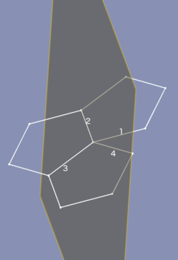
Specialty mode for folding polyhedra. Select 4 edge in order: foldable edge, fold line, other fold line, other foldable edge. Plane will be aligned to folding the first edge. In the picture below, it is not required that both leafs to fold together be the same .
Inertia 2-3
Object will be attached to a plane passing through second and third principal axes of inertia (passes through center of mass) .
- Reference combinations
- Any
- Any, Any
- Any, Any, Any
- Any, Any, Any, Any
Attachment Offset
Attachment Offset is used to apply a linear or rotary offset from the referenced object. It becomes active when an attachment mode other than Deactivated has been selected .
- X: sets an offset distance in the X axis of the reference object .
- Y: sets an offset distance in the Y axis of the reference object .
- Z: sets an offset distance in the Z axis of the reference object .
- Yaw: rotates the attached object along the reference object's Z axis .
- Pitch: rotates the attached object along the reference object's Y axis .
- Roll: rotates the attached object along the reference object's X axis .
- Flip sides: if checked, the attached object is reversed from its XY plane .
