DiseñoPiezas Rotación
|
|
| Ubicación en el Menú |
|---|
| PartDesign -> Revolution |
| Entornos de trabajo |
| PartDesign, Complete |
| Atajo de teclado por defecto |
| Ninguno |
| Introducido en versión |
| - |
| Ver también |
| Ninguno |
|
|
| Ubicación en el Menú |
|---|
| PartDesign -> Revolution |
| Entornos de trabajo |
| PartDesign, Complete |
| Atajo de teclado por defecto |
| Ninguno |
| Introducido en versión |
| - |
| Ver también |
| Ninguno |
Introducción
Esta herramienta revoluciona un croquis seleccionado u objeto 2D alrededor de un eje dado.
Options
When creating a revolution, the 'revolution parameters' dialogue offers several parameters specifying how the sketch should be revolved.
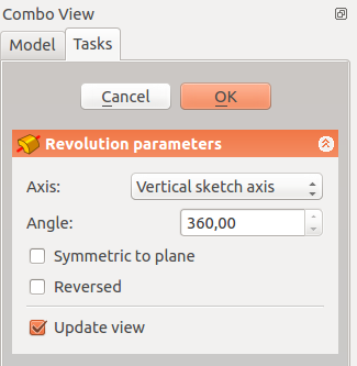 |
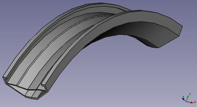
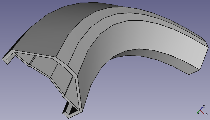
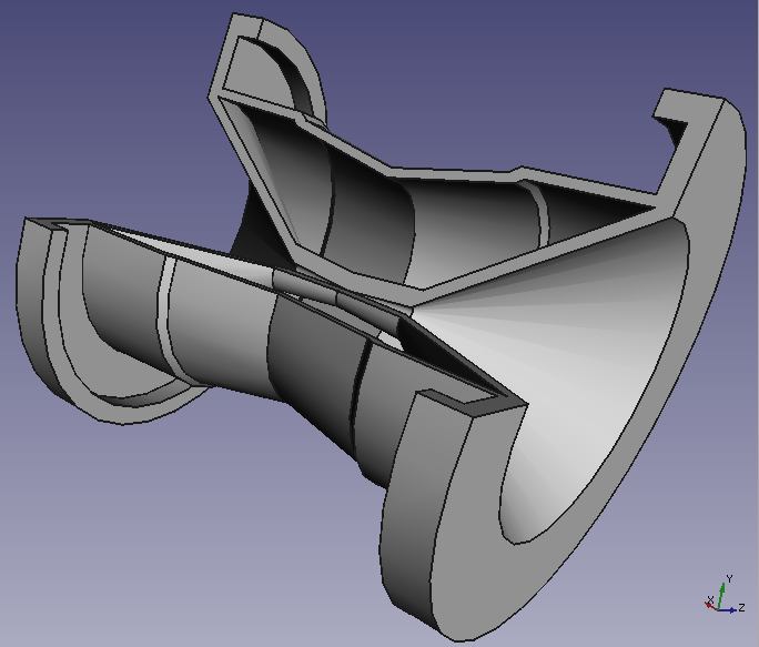
AxisThis option specifies the axis about which the sketch is to be revolved. Currently, by default only the horizontal or vertical sketch axis can be selected here. However if the sketch which defines the feature to be Revolved also contains a construction line (or lines), then the drop down list will contain one custom sketch axis for each construction line. The first construction line will be labelled 'Sketch axis 0'. After creation an arbitrary axis can be defined in the Properties table. Base is a point through which the axis goes. The axis option itself takes three arguments, which are passed as numbers to either the x, y, or z boxes in the tool. Adding a value of 1.0 to only one of the boxes will cause the tool to make the revolution about that axis. Example revolutions 1, 2 and 3 in the examples section demonstrate scenarios where the example sketch is revolved about either the x or the y axis. Adding a non-zero value to more than one of the axes will cause the part to be revolved by a weighted amount in each axis. e.g. an x value of 1 and a y value of 2 will mean that the revolution about the y-axis is twice as strong as that about the x. This is fairly difficult to comprehend, Example Revolution 4 shows an example where more than one of the boxes has a non-zero value. AngleThis controls the angle through which the revolution is to be formed, e.g. 360° would be a full, contiguous revolution. The images in the examples section demonstrate some of the possibilities with specifying different angles. It is not possible to specify negative angles (use the Reversed option instead) or angles greater than 360°. Symmetric to planeThe revolution will extend half of the specified angle in both directions from the sketch plane. ReversedThe direction of revolution will be reversed. |
Examples

Note: Unlike the above, all these examples below refer to Base, Axis and Placement being edited directly through the feature properties table.
Useful links
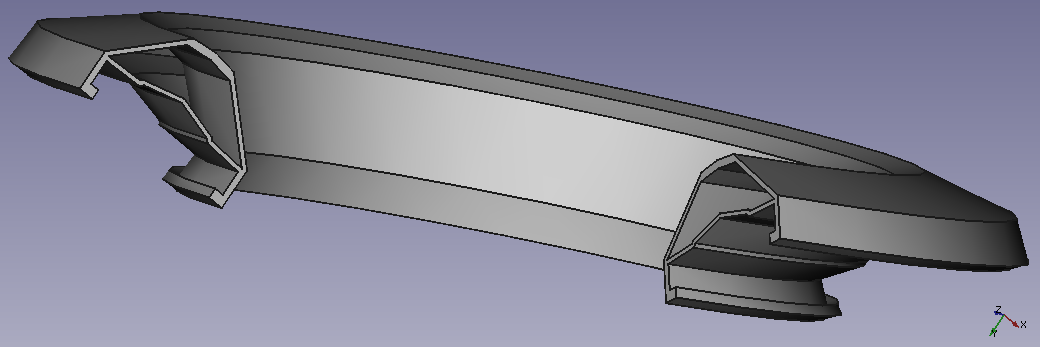
An example with the practice on the forum.