PartDesign Revolution/es: Difference between revisions
(Updating to match new version of source page) |
(Updating to match new version of source page) |
||
| Line 12: | Line 12: | ||
# Select the sketch to be revolved. <span style="font-size:x-small;color:green;">v0.17 and above</span> A face on the existing solid can alternatively be used. |
# Select the sketch to be revolved. <span style="font-size:x-small;color:green;">v0.17 and above</span> A face on the existing solid can alternatively be used. |
||
# Press the {{KEY|[[Image: |
# Press the {{KEY|[[Image:PartDesign Revolution.png|24px]] '''Revolution'''}} button. |
||
# Set the Revolution parameters (see next section). |
# Set the Revolution parameters (see next section). |
||
# Press {{KEY|OK}}. |
# Press {{KEY|OK}}. |
||
Revision as of 20:03, 28 February 2018
|
|
| Ubicación en el Menú |
|---|
| PartDesign -> Revolution |
| Entornos de trabajo |
| PartDesign, Complete |
| Atajo de teclado por defecto |
| Ninguno |
| Introducido en versión |
| - |
| Ver también |
| Ninguno |
Introduction
This tool revolves a selected sketch or 2D object about a given axis. For all the following explanations of this command the example sketch below will be used:
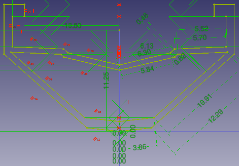

Above: sketch (A) is revolved 270 degrees counter-clockwise around axis (B); resulting solid (C) is shown right.
How to use
- Select the sketch to be revolved. v0.17 and above A face on the existing solid can alternatively be used.
- Press the
 Revolution button.
 - Set the Revolution parameters (see next section).
- Press OK.
Para todas las siguientes explicaciones de este comando se utilizará el croquis de abajo:

Opciones
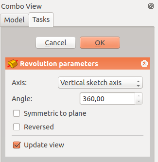
Cuando se crea una revolución, el letrero de diálogo de 'parámetros de revolución' ofrece varios parámetros especificando como se debería revolucionar el croquis.
Eje
Esta opción especifica el eje alrededor del cual se hace revolucionar el croquis. Actualmente, sólo se pueden seleccionar los ejes horizontal o vertical. Pero en la tabla de propiedades, puede definirse un eje arbitrario. Base es un punto a través del cual pasa el eje. La opción ejes en si misma toma tres argumentos, que son pasados como números a las casillas X, Y, Z en la herramienta. Añadiendo un valor de 1.0 a sólo una de las casillas casará que la herramienta cree la revolución sobre ese eje. Los ejemplos de revoluciones 1, 2 y 3 en la sección de Ejemplos muestran escenarios donde el croquis de ejemplo se revoluciona sobre el eje X o el Y. Añadiendo un valor distinto a cero a más de uno de los ejes hará que la pieza sea revolucionada por una determinada cantidad en cada eje. Por ejemplo, un valor en X de 1 y en Y de 2 significará que la revolución sobre eje Y será el doble de fuerte que sobre el eje X. Esto es bastante dificil de comprender, el ejemplo de revolución 4 muestra un caso de este tipo
Base
Esta opción especifica la equidistancia en los ejes X, Y o Z y acepta cualquier número como argumento. Para los croquis de ejemplo de esta página, introduciendo un valor de -100 para el campo Y se equidistanciará el croquis -100mm en el eje Y. La diferencia entre una equidistancia en el eje Y de 0 o de -100 se ilustra en las imágenes 1 y 3 del ejemplo de revolución (más abajo). La imagen 1 tiene un valor de equidistancia sobre el eje Y de -100, y en la imagen 3 es de 0.
Situación
Una vez el croquis se ha revolucionado, se transforma en una pieza revolucionada. Esta sección controla la situación de la pieza con respecto al sistema de coordenadas. NOTA: Las siguientes opciones no afectan a las dimensiones físicas de la pieza (tal como hacen las de arriba), pero modifican su posición en el espacio.
Ángulo
El argumento del ángulo especifica el ángulo a utilizarse con la opción Eje. Un ángulo se establece aquí, y el eje actúa sobre el ángulo actúa se establece con la opción Eje. La pieza es girada el ángulo especificado alrededor del eje especificado. Un ejemplo de utilización podría ser si creas la revolución, pero luego necesitas girar la pieza una cantidad definida, para permitir que se alinee con otra pieza preexistente.
Eje
Esta opción especifica el eje sobre el cual la pieza de revolución creada será girado - NO REVOLUCIONADO. El valor exacto de rotación viene de la opción de ángulo (arriba). Esta opción toma tres argumentos, que se pasan como números a las casillas X, Y y Z. Añadiendo un valor a más de uno de los ejes hará que la pieza sea girada por el ángulo definido en cada eje. Por ejemplo, con un ángulo de 15° establecido, especifica unos valores de 1.0 y 2.0 para los valores X e Y del Eje causará que la pieza terminada sea girada 15º en el eje X y 30º en el eje Y.
Posición
Ejemplos
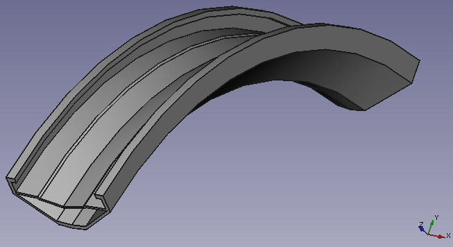
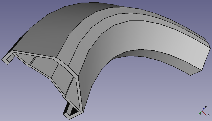
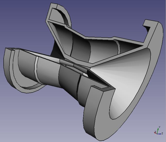
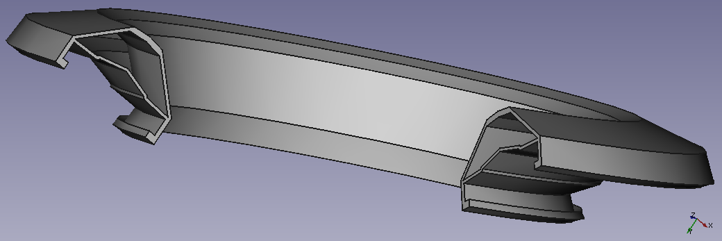
 |
AxisThis option specifies the axis about which the sketch is to be revolved. Currently, by default only the horizontal or vertical sketch axis can be selected here. However if the sketch which defines the feature to be Revolved also contains a construction line (or lines), then the drop down list will contain one custom sketch axis for each construction line. The first construction line will be labelled 'Sketch axis 0'. After creation an arbitrary axis can be defined in the Properties table. Base is a point through which the axis goes. The axis option itself takes three arguments, which are passed as numbers to either the x, y, or z boxes in the tool. Adding a value of 1.0 to only one of the boxes will cause the tool to make the revolution about that axis. Example revolutions 1, 2 and 3 in the examples section demonstrate scenarios where the example sketch is revolved about either the x or the y axis. Adding a non-zero value to more than one of the axes will cause the part to be revolved by a weighted amount in each axis. e.g. an x value of 1 and a y value of 2 will mean that the revolution about the y-axis is twice as strong as that about the x. This is fairly difficult to comprehend, Example Revolution 4 shows an example where more than one of the boxes has a non-zero value. AngleThis controls the angle through which the revolution is to be formed, e.g. 360° would be a full, contiguous revolution. The images in the examples section demonstrate some of the possibilities with specifying different angles. It is not possible to specify negative angles (use the Reversed option instead) or angles greater than 360°. Symmetric to planeIf checked, the revolution will extend half of the specified angle in both directions from the sketch plane. ReversedIf checked, the direction of revolution is reversed from default clockwise to counterclockwise. |
Examples

For all the following example uses, the example sketch below will be used:

Note: Unlike the above, all these examples below refer to Base, Axis and Placement being edited directly through the feature properties table.


Useful links
A detailed example of use on the forum.