PartDesign Lagergehäuse Tutorium II
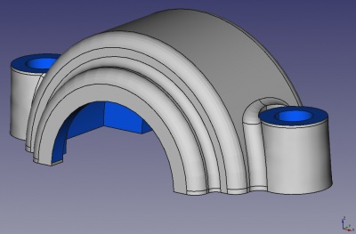
Wie der Warnhinweis oben auf der Seite bereits andeutet, funktioniert dieses Tutorial NICHT, es sei denn, du kompilierst einen speziellen, sehr experimentellen Zweig aus dem FreeCAD Quellcode und ist ein einführendes Tutorial zur Modellierung mit dem PartDesign Arbeitsbereich in FreeCAD unter Verwendung von Datumsebenen, die in den meisten FreeCAD Versionen noch nicht vorhanden sind. Der Zweck des Tutoriums ist es, dich in zwei verschiedene Arbeitsabläufe zur Erstellung eines Gussteils mit Entwürfen und Verrundungen einzuführen. Je nachdem, welche anderen CAD Programme du bisher verwendet hast, könnte dir das eine oder das andere vertraut sein. Als Arbeitsbeispiel werden wir ein einfaches Lagergehäuse modellieren.
Dies ist der zweite Teil des Tutoriums. Es wird der so genannte "Multikörper" Arbeitsablauf verwendet, wobei der (einfachere) obere Teil des Gehäuses als Beispiel dient.
Selbstverständlich musst du zum Durcharbeiten dieses Tutorials den PartDesign Arbeitsbereich aktivieren.
Du findest meine Version des von diesem Tutorium erstellten Teils [hier]. Die Datei ist nicht mehr verfügbar, eine neue wird zu einem späteren Zeitpunkt bereitgestellt werden.
Konstruktionsdaten
Das Gehäuse sollte in der Lage sein, ein Lager mit einem Durchmesser von 90 mm und einer Breite von bis zu 33 mm aufzunehmen (z.B. DIN 630 Typ 2308 mit einem Innendurchmesser von 40 mm). Das Lager erfordert eine Schulterhöhe von mindestens 4,5 mm im Halter (und auf der Welle). Der obere Teil des Gehäuses wird mit zwei 12mm Schrauben an der Unterseite verschraubt. Der Kopf einer solchen Schraube benötigt einen Freiraum von mindestens 20 mm Durchmesser. Auf beiden Seiten des Lagers sollte eine Nut vorhanden sein, die einen Standard-Wellendichtring DIN 3760 aufnehmen kann: 38x55x7 oder 40x55x7 auf der einen Seite, 50x68x8 auf der anderen Seite.
Das Gehäuse wird ein Sandguss mit einer Mindestwandstärke von 5 mm, einem Entformungswinkel von 2 Grad und einem minimalen Verrundungsradius von 3 mm sein.
Einrichten der Skelettgeometrie
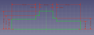
Erstelle im PartDesign Arbeitsbereich ein neues Teil. Benenne den standardmäßig erstellten Körper in Skeleton um. Dieser Körper ist wahrscheinlich bereits aktiviert, was du an der blauen Hintergrundfarbe im Formelementebaum erkennen kannst. Erstelle eine neue Skizze auf der YZ Ebene, die den Umriss der Welle, des Lagers und der Dichtungsringe enthält. Nachdem du die Skizze fertiggestellt hast, erstelle daraus ein Rotations Formelement. Dieses Skelettformelement wird später dazu verwendet, die reale Geometrie darauf zu beziehen. Das bedeutet, dass du, wenn du irgendwelche Bemaßungen ändern möchtest, nur die Bemaßungen des Skelettformelements anpassen musst, und der Rest des Teils wird entsprechend aktualisiert.
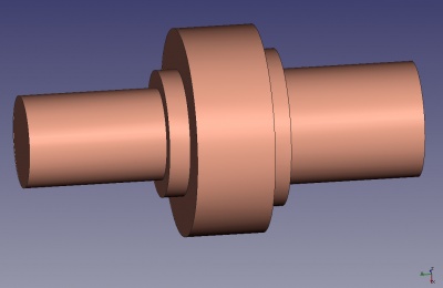
Der Hauptkörper
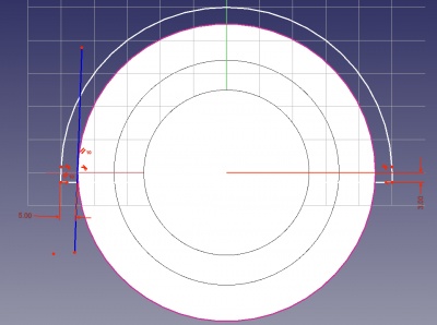
Erstelle einen neuen Körper und mache ihn aktiv. Die Skizze für den ersten Block ist rechts abgebildet. Er wird auf einer Bezugsebene mit einem Versatz von 5 mm (Wandstärke) von der Skelettfläche platziert, die die Seite eines der tragenden Dichtungsringe markiert. Da alle wichtigen Maße vom Skelett abgenommen werden, gibt es nur drei Maße: Die Bearbeitungszugabe (3 mm) an der Basis als Versatz zur XY Ebene, die 5 mm Wanddicke vom Außendurchmesser des Skeletts und der Entformungswinkel von zwei Grad. Zwei erzeugen die 5mm Bemaßung, du musst zuerst den Außenkreis (Radius 45mm) der Skelettgeometrie als Außengeometrie im Skizzierer auswählen und dann eine tangential zu diesem Kreis und in einem Winkel von zwei Grad gebundene Konstruktionslinie einfügen.
Du fragst dich wahrscheinlich, warum sich am unteren Ende jedes Bogens dieses kleine gerade Segment befindet. Dieses Segment sorgt dafür, dass auf den Bögen ein Entformungswinkel von 2 Grad entsteht. Das mag nach viel Arbeit für einen sehr kleinen Nutzen aussehen, aber viele CAD Programme (und vielleicht eines Tages auch FreeCAD) haben Werkzeuge, die ein Volumenmodell in verschiedenen Farben hervorheben und dir sofort alle Flächen anzeigt, bei denen der Entformungswinkel nicht korrekt ist. Du willst nicht, dass das mit deinem Modell passiert, besonders nachdem du viele Verrundungen angebracht hast!
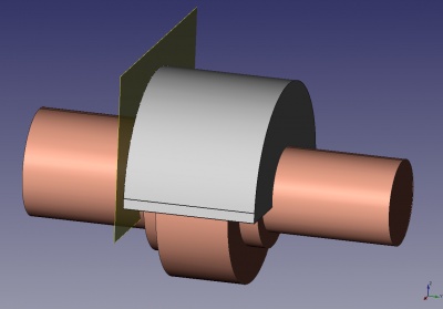
Wenn du die Skizze angefertigt hast (was wegen der 2 Grad Tangentiallinien etwas knifflig ist), erstelle daraus ein Polster, das sich bis zur anderen Seite der Skelettgeometrie erstreckt, wiederum mit einem Versatz von 5 mm zur Seitenfläche. du brauchst diesmal keine Bezugsebene zu erzeugen, der "bis zur Fläche" Modus des Polster Dialogs bietet die Eingabe eines Versatzes an.
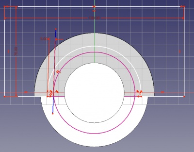
Next, we will cut away some material on both ends of the Pad because it is always ideal for cast parts to have as uniform a wall thickness as possible. Create a sketch on each of the end faces of the Pad and dimension it at 5mm offset from the circle representing the bearing sealing ring (radius 27.5mm on one side and 34mm on the other). For the bottom line segment of the sketch, create another external geometry from the Pad and constrain to this. Thus the sketch has only a single dimension, the 5mm wall thickness (the 150mm and 75mm dimensions are not important as long as they are large enough to ensure that everything is cut away).
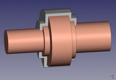
Use the sketch you created to make a Pocket and extend it to the face of the skeleton geometry that represents the bearing, minus 5mm offset for the wall thickness. For the second Pocket, you can use the option "Duplicate selected object" from the Edit menu to duplicate the sketch you already made (choose not to duplicate dependend objects if the question pops up). Then, select the face you want to move this sketch to, and tell FreeCAD to map the sketch to this face (this is an item on the PartDesign menu). After creating the second Pocket, you can look at the result from the bottom to check that you have a uniform wall thickness of 5mm around the contour of the skeleton geometry.
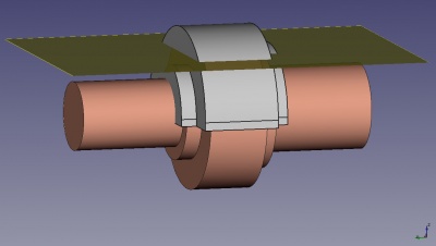
Now it's time to create draft and fillets. The draft feature requires a neutral plane, meaning that the geometry that is cut by this plane will remain in its place, while the rest of the face is tilted at the draft angle. Using the bottom of the Pad for this purpose for this is not a good idea, because the wall thickness in the top part of the holder would become less than 5mm. So we create a datum plane offset about 35mm from the XY for this purpose. Activate the Skeleton body and create the plane there, because we will need it for applying draft to other bodies, too.
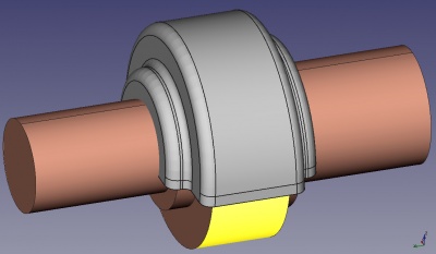
The picture on the right shows the finished first body with draft and fillets applied. Note that the outer (concave) edges have a larger fillet radius of 5mm, again with the purpose of creating a more uniform wall thickness (more than 5mm is not possible because then after machining the inside of the holder the wall thickness would become less than 5mm).
Hinzufügen der Körper für die Schrauben
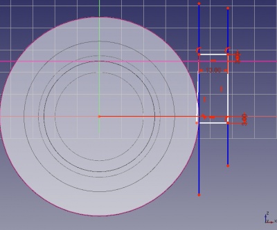
The bolts need two cylindrical bodies on both sides of the main Body. It is best to include the 2 degree draft angle in the sketch. I tried revolving a cylinder and later applying a draft, but weird things happened after mirroring it and I couldn't put fillets on it because the surface was warped somehow.
The sketch is dimensioned so that the rotation axis is 12mm distance to the outer diameter of the skeleton Body, 7mm for the radius of the hole plus 5mm for the wall thickness. For the sake of having a fully parametric part, it is a good idea to add a plane to the Skeleton about 25mm above the XY-plane to mark the top of the cylinders. Since this will be machined, the sketch is dimensioned 3mm above it.
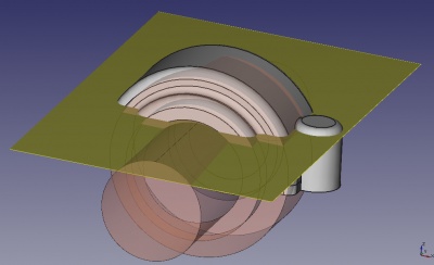
Create a revolution from the sketch and apply a fillet of 4mm to the top. This means that after machining away 3mm, a slight radius will remain which helps to avoid a sharp edge where someone could cut their hand when tightening the bolt.

Create a boolean feature to fuse the main Body and the bolt body. Then create a new body for the other side. Duplicate the sketch of the revolution, move it to this body and create the second body for the bolts (mirroring a Body is not supported yet so you need to redo most of it). Then fuse this second body into the main Body as well. Finally, apply a large fillet on the edge created by the boolean fuse operation. The largest I could get was 4mm.
Aushöhlung des Hauptkörpers
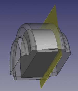
We will now work on the inside of the holder and hollow it out to make space for the bearing and sealing rings. When doing this of course we need to keep in mind the 3mm machining allowance. Since this tutorial teaches the multi-body method, we will create the inside geometry as a separate body and then cut it out of the main body with a boolean operation.
Create a new body and make it active. First, we need a datum plane offset 3mm inside the skeleton face that shows the side of the bearing. Then, duplicate the sketch of the first Pad of the main body. It will be added to the main body, so right-click on it and choose to move it to the newly created body (this option is only available in the context menu if the PartDesign workbench is active). Map the sketch onto the datum plane (if the sketch turns upside-down after mapping, move the datum plane to the other side of the bearing, next to where the duplicated sketch is located). Now, modify the sketch so that the diameter is 3mm less than the outer diameter of the skeleton geometry that represents the bearing. All you need to do is remove the 5mm dimension, drag the sketch inside the reference circle, and create a new 3mm dimension.
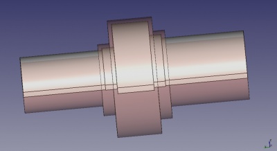
Next we want two more Pads to hollow out the place for the sealing rings. Duplicate the sketch of the first pad of the cut-out Body and map it to the XZ-plane. Edit the sketch and replace the external reference with the outer diameter of the bearing sealing ring. Extrude this sketch to an offset of 3mm of the side of the sealing ring. Repeat the whole process for the sealing ring on the other side.
After this we want to create two more Pads like the last two to give the shaft a clearance (e.g. 3mm) inside the holder.
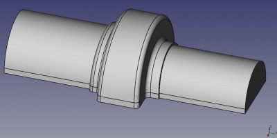
Now all that remains is to apply draft to the planar side faces, using the same neutral plane as for the main body, and filleting. Apply a general fillet of 3mm to all edges. You will notice that there are several edges that cannot be filleted... this is a defect of the underlying geometric kernel which FreeCAD uses.
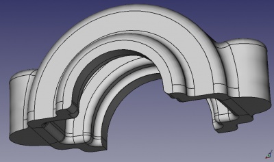
We are ready to hollow out the main body. Select it and choose to create a new Boolean operation. Add the cut-out body to the list window and set the operation to "Cut". Put a 3mm fillet on the two edges resulting from the cut-out operation (again some edges remain that are "unfilletable"). The result should look like the picture on the right.
The raw part is now completed. This is what the holder will look like before machining. Note that since the mold will have a top and bottom half, the edge between these two cannot be filleted. Also, if you give away this model to a foundry make sure to point out that it has the dimensions after casting. The foundry will then have to apply a certain percentage of shrinkage to the model (making the digital model used to manufacture the mold larger so that when the metal cools down and shrinks after casting it will have the right size).
Spanende Bearbeitung
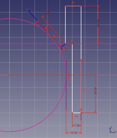
To take away the material for machining the inside of the holder, very conveniently we can use the Skeleton Body itself. If you don't want that because then the skeleton gets hidden somewhere deep in the tree, you can also duplicate the sketch of the skeleton Revolution feature and re-create the revolution in another body. This is not completely parametric, though, because the duplicated sketch is independent of the original, so you will have to work on both if you change a dimension. Dependent duplicated features might be supported in the future sometime.
For the rest of the machining, create a new Body. The bottom of the holder will be machined by a Pad sketched on the XY-plane extending downwards. Next, sketch a revolution to make a hole for the bolts. You will need to sketch on the XZ-plane and revolve it so that you can choose the outer diameter of the skeleton Body as an external reference. The top part of the sketch will serve to machine a flat place for the head of the bolt. It is dimensioned to leave at least 5mm wall thickness in the holder. If this does not give enough space for the bolt head then you can move the datum plane upwards. Of course, you could put this logic into the Skeleton, which is left as an exercise to the reader!
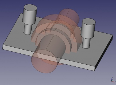
You can mirror the revolution on the YZ-axis. The picture on the right shows the "machining" Body. Of course, most of the dimensions of the Pads and Revolutions are not important as long as there is plenty of overlap.

Finally, create a boolean operation to cut the machining Body out of the main Body. If you want a nice visual effect, you can colour the machined surfaces differently from the rest of the part. This is also a useful optical feedback showing you whether you forgot to machine somewhere.