Manuale:Generare disegni 2D
- Introduzione
- Scoprire FreeCAD
- Lavorare con FreeCAD
- Script Python
- La Comunità
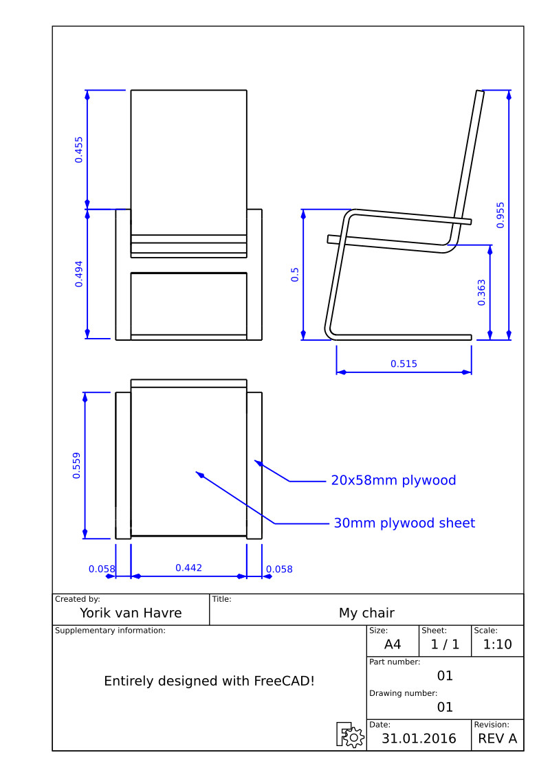
Quando il modello non può essere stampato o fresato direttamente da una macchina, perchè, ad esempio, è troppo grande (un edificio) o richiede il montaggio manuale quando i pezzi sono pronti, di solito bisogna spiegare ad un'altra persona come fare. Nel campo tecnico (ingegneria, architettura, ecc), questo di solito viene fatto con dei disegni che spiegano come farlo, e che vengono consegnati al responsabile dell'assemblaggio del prodotto finale.
Esempi tipici sono Ikea instructions, architectural drawings o blueprints. Questi disegni di solito contengono non solo i disegni stessi, ma anche molte annotazioni, quali testi, dimensioni, numeri, simboli che aiutano a capire che cosa deve essere fatto e come.
In FreeCAD, l'ambiente di lavoro responsabile della produzione di tali disegni è Drawing.
L'ambiente Drawing consente di creare dei fogli, che possono essere vuoti o utilizzare un modello predefinito che ha già una serie di elementi, come i bordi e il titolo. Su questi fogli, si possono quindi posizionare le viste degli oggetti 3D modellati in precedenza, e configurare come queste viste devono apparire sul foglio. Infine, grazie ad un addon chiamato Drawing Dimensioning Workbench, sul foglio è anche possibile effettuare tutti i tipi di annotazioni, come le dimensioni, testi e altri usuali simboli comunemente usati nei disegni tecnici.
I fogli di disegno, una volta completi, possono essere stampati o esportati come file SVG, PDF o DXF.
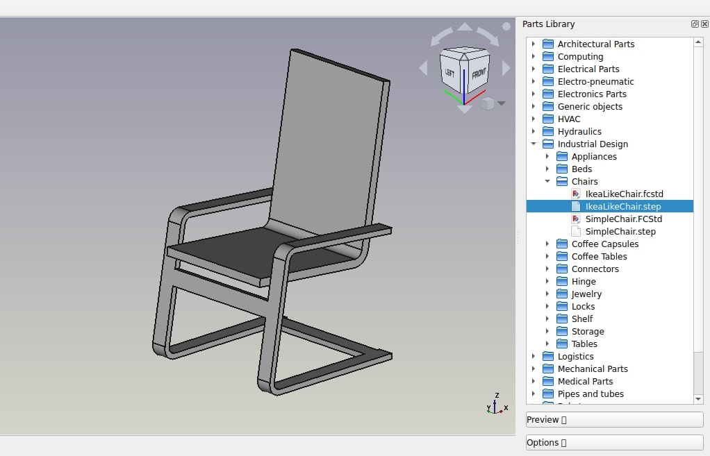
Nel seguente esercizio, vedremo come creare un semplice disegno di un modello di sedia trovato in FreeCAD library (Furniture -> Chairs -> IkeaChair). La libreria FreeCAD può essere facilmente aggiunta alla propria installazione FreeCAD (consultare il capitolo installazione di questo manuale), oppure si può semplicemente scaricare il modello dalla libreria della pagina web, oppure tramite il link diretto fornito in fondo a questo capitolo.
- Load the IkeaChair file from the library. You can choose between the .FCStd version, which will load the full modeling history, or the .step version, which will create only one object, without the history. Since we won't need to model any further now, it is best to choose the .step version, as it will be easier to manipulate.
- Switch to the Drawing Workbench
- Press the little arrow next to the
 New Drawing Page button.
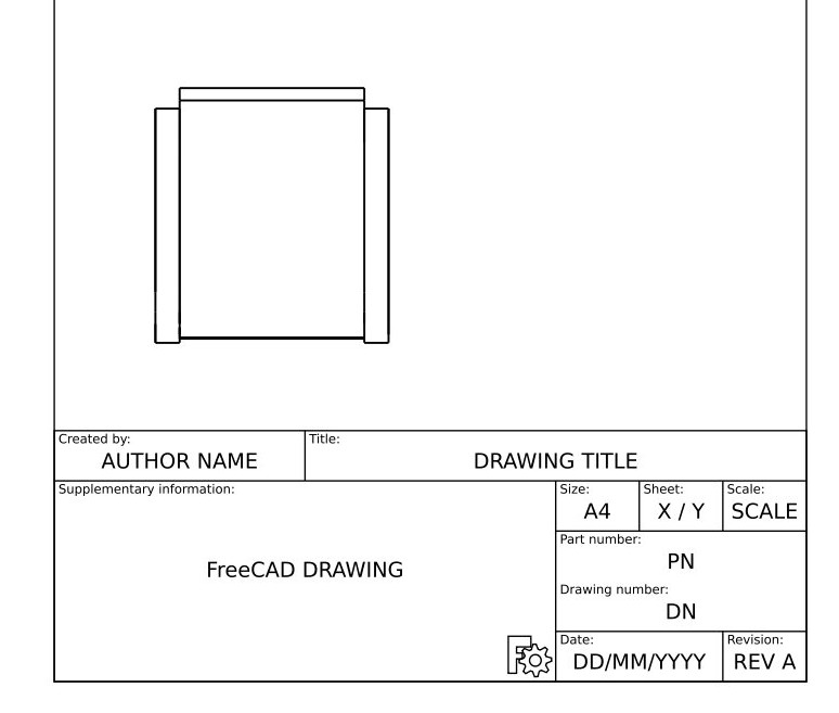
 - Select the A4 Portrait / ISO7200 template. A new tab will open in your FreeCAD window, showing the new page.
- In the tree view (or in the model tab), select the chair model.
- Press the
 Insert view button.
 - A View object will be created on our page. Give the view the following properties:
- X: 100
- Y: 150
- Scale: 0.1
- Rotation: 270
- We now have a nice top view (which is the default projection) of our chair:
- Let's repeat the operation twice, to create two more views. We will set their X and Y values, which indicate the position of the view on the page, in order to show them apart from the top view, and their direction, to create different view orientations. Give each new view the following properties:
- View001 (front view): X: 100, Y: 130, Scale: 0.1, Rotation: 90, Direction: (-1,0,0)
- View002 (side view): X: 180, Y: 130, Scale: 0.1, Rotation: 90, Direction: (0,-1,0)
- After that, we obtain the following page:
- We can tweak a bit the aspect of our views if we want, for example we can raise their Line Width property to 0.5.
We will now place dimensions and indications on our drawing. There are two ways to add dimensions to a model, one is placing the dimensions inside the 3D model, using the ![]() Dimension tool of the Draft Workbench, and then place a view of these dimensions on our sheet with the
Dimension tool of the Draft Workbench, and then place a view of these dimensions on our sheet with the ![]() Draft View tool (which can be used with a single dimension or a group containing dimensions), or we can do things directly on the Drawing sheet, using the Drawing Dimensioning Workbench, which is installable from the FreeCAD addons. We will use here this latter method.
Draft View tool (which can be used with a single dimension or a group containing dimensions), or we can do things directly on the Drawing sheet, using the Drawing Dimensioning Workbench, which is installable from the FreeCAD addons. We will use here this latter method.
- Switch to the Drawing Dimensioning Workbench
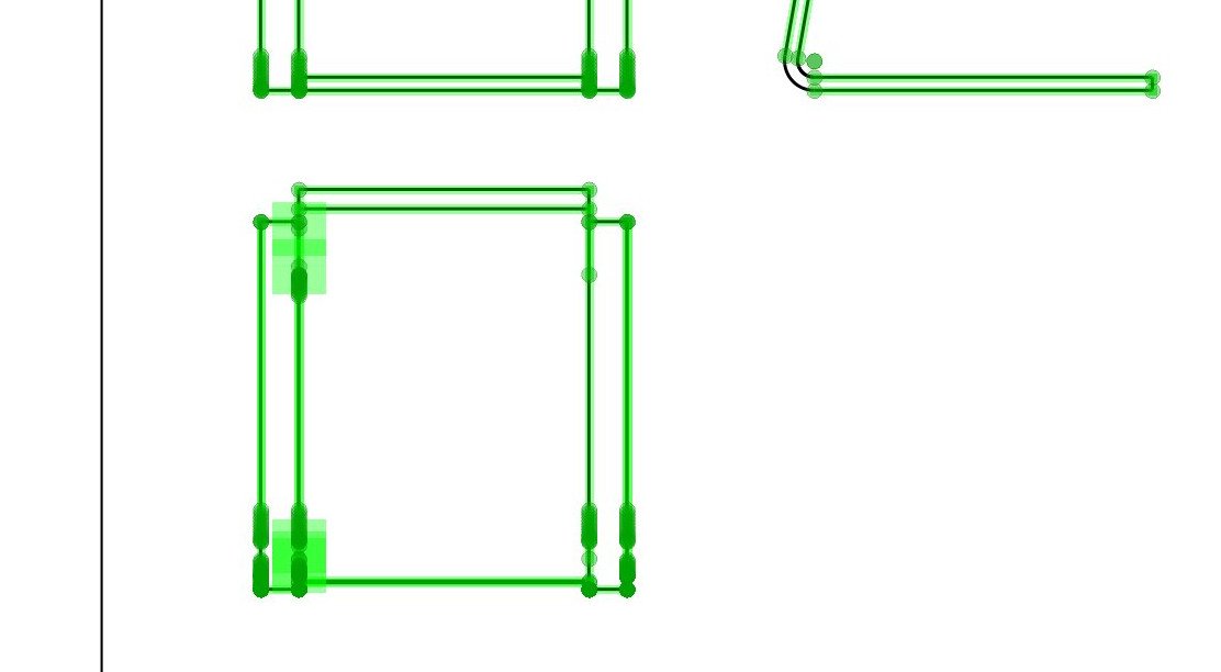
- Press the Add Linear Dimension button. Available nodes are highlighted in green on the drawing page:
- Click two of these points, then click a third point to place the dimension line:
- The Linear Dimension tool, as most of the other Drawing Dimensioning tools, will not exit after you finished, allowing you to place more dimensions. When you are done, simply click the Close button in the Task panel.
- Repeat the operation, until all the dimensions you wish to indicate are placed. Take a minute to browse through the different options proposed in the Linear Dimension's task panel. For example, by unticking the auto place text option, you will be able to place the text of the dimension elsewhere, like on the image below:
- We will now place two indications, using the Welding/Groove symbols tool, selecting the default one (no groove symbol). Draw the two lines like on the image above.
- Now place two texts using the Add text tool, and change their text property to the contents of your likings.
- Our drawing is now complete, all that is left to do is to fill in the informations of the sheet titleblock. With most of the default FreeCAD templates, this can be done easily, by changing the Editable Texts property of the page.
Our page can now be exported to SVG to be worked further in graphical applications like inkscape, or to DXF by selecting menu File -> Export. The Drawing Dimensioning workbench also features its own DXF export tool, which also supports the annotations added with that workbench. The DXF format is importable in almost all existing 2D CAD applications. Drawing pages can also be directly printed or exported to PDF.
Downloads
- The chair model: https://github.com/FreeCAD/FreeCAD-library/blob/master/Furniture/Chairs/IkeaLikeChair.step
- The file created during this exercise: https://github.com/yorikvanhavre/FreeCAD-manual/blob/master/files/drawing.FCStd
- The SVG sheet produced from that file: https://github.com/yorikvanhavre/FreeCAD-manual/blob/master/files/drawing.svg
Read more


