Manual:Creating FEM analyses/ru: Difference between revisions
(Created page with "* Загрузим [https://github.com/yorikvanhavre/FreeCAD-manual/blob/master/files/house.FCStd модель дома], которую мы сделали ранее * Уд...") |
(Created page with "* Верстак FEM пока может вычислить деформацию лишь единого объекта. Поэтому нам надо объединить н...") |
||
| Line 24: | Line 24: | ||
[[Image:Exercise_fem_02.jpg]] |
[[Image:Exercise_fem_02.jpg]] |
||
* |
* Верстак FEM пока может вычислить деформацию лишь единого объекта. Поэтому нам надо объединить наши два объекта, стены и плиту. Переключимся на [[Part_Module/ru|верстак Part]], выделим оба объекта и нажмём [[Image:Part_Union.png|16px]] [[Part_Union/ru|Union]]. Теперь мы получили объединённый объект: |
||
[[Image:Exercise_fem_03.jpg]] |
[[Image:Exercise_fem_03.jpg]] |
||
Revision as of 06:52, 5 April 2017
- Введение
- Открываем для себя FreeCAD
- Работа с FreeCAD
- Все верстаки одним взглядом
- Традиционное моделирование методом КБГ
- Традиционное двумерное черчение
- Моделирование для проектирования продукта
- Подготовка для объёмной печати
- Создание двумерных чертежей
- Моделирование BIM
- Использование электронных таблиц
- Создание анализа методом конечных элементов
- Визуализация проекта
- Написание скриптов на Python
- Сообщество
Метод конечных элементов (сокращённо МКЭ) это большой раздел математики, но в FreeCAD мы подразумеваем его как способ подсчитать разспространение воздействий в объёмном объекте нарезанием его на малые участки, и анализируя влияние каждого элемента на своих соседей. У него есть много приложений в проектировании и электромагнитных полях, но здесь мы будем углубляться в то, что используется в FreeCAD, расчёт деформаций объектов под воздействием силы и веса.
Получение такого моделирования в FreeCAD сделано в верстаке FEM. Оно включает различные шаги: подготовка геометрии, установка материала, создание полигональной сетки, деление на малые участки, как это делалось в главе Подготовка для объёмной печати, и в конце калькуляция модели.
Подготовка FreeCAD
Моделирование производится сторонней программой, используемой FreeCAD для получения результатов. Поскольку симуляторов для моделирования по МКЭ с открытыми исходными кодами несколько, верстак FEM сделан способным использовать несколько из них. Тем не менее, пока полностью поддерживается только CalculiX. Так же для генерации разделяющей сетки требуется другая программа, NetGen. Детальная инструкция для установки этих двух компонентов дана в документации FreeCAD.
Подготовка геометрии
Начнём с дома, который мы моделировали в разделе Моделирование BIM. Нам потребуются некоторые изменения для приспособления модели к расчёту по МКЭ. В это входит исключение объектов, которые мы не хотим учитывать при вычислении, таких как двери и окна, и объединение всех остальных объектов в один.
- Загрузим модель дома, которую мы сделали ранее
- Удалим или скроем страницу, сечения и виды сверху с размерными линиями, оставив только саму модель
- Скроем окно, дверь и плиту пола
- Так же скроем металлические балки крыши. Поскольку они сильно отличаются от остального дома, этим исключением мы упростим наши вычисления. Вместо этого мы предположим что плита крыши напрямую положена на стены.
- Теперь положим плиту крыши вниз, чтобы она легла на верх стен: Редактируем объект Rectangle, который взят как база для плиты, и изменим его параметр Placement->Position->X с 3.18m на 3.00m
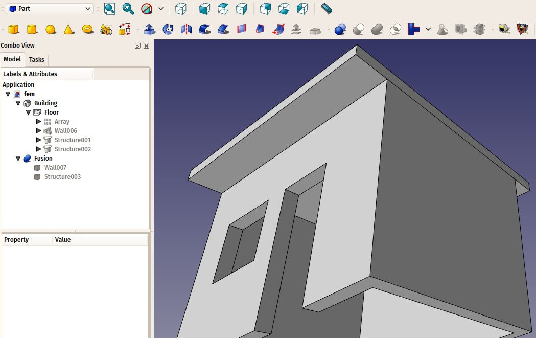
- Теперь наша модель очищена:
- Верстак FEM пока может вычислить деформацию лишь единого объекта. Поэтому нам надо объединить наши два объекта, стены и плиту. Переключимся на верстак Part, выделим оба объекта и нажмём
 Union. Теперь мы получили объединённый объект:
Creating the analysis
- We are now ready to start a FEM analysis. Let's switch to the FEM Workbench
- Select the fusion object
- Press the
 New Analysis button
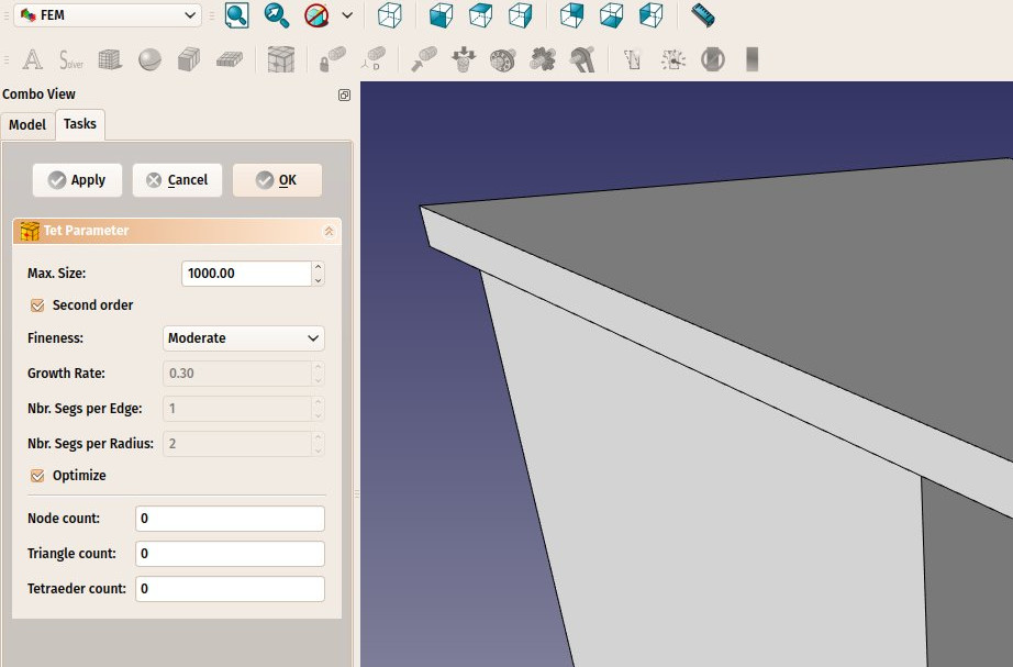
 - A new analysis will be created and a settings panels opened. Here you can define the meshing parameters to be used to produce the FEM mesh. The main setting to edit is the Max Size which defines the maximum size (in millimeters) of each piece of the mesh. For now, we can leave the default value of 1000:
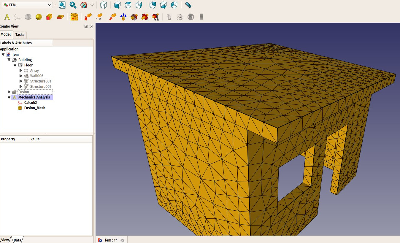
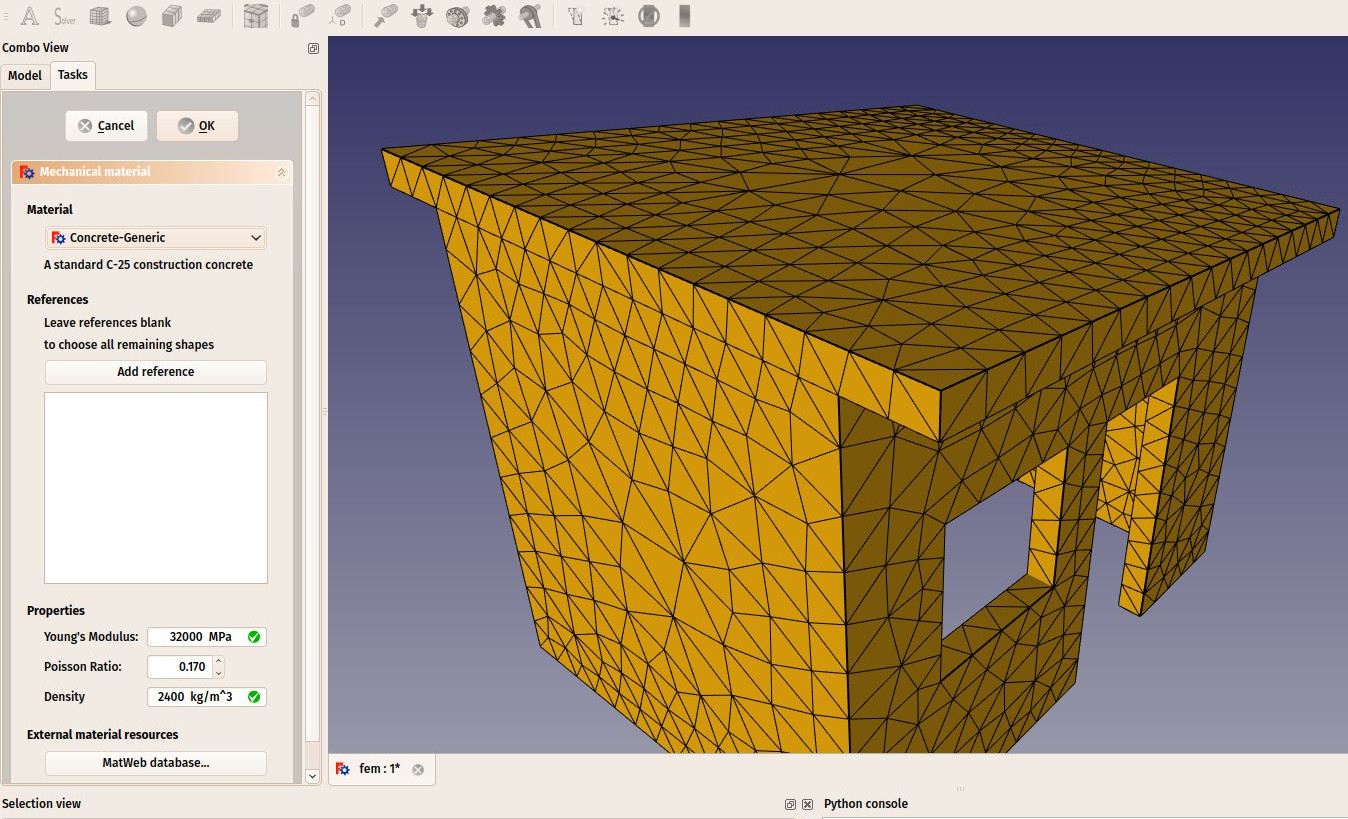
- After pressing OK and a few seconds of calculation, our FEM mesh is now ready:
- We can now define the material to be applied to our mesh. This is important because depending on the material strength, our object will react differently to forces applied to it. Select the analysis object, and press the File:Fem MechanicalMaterial.png New Material button.
- A task panel will open to allow us to choose a material. In the Material drop-down list, choose the Concrete-generic material, and press OK.
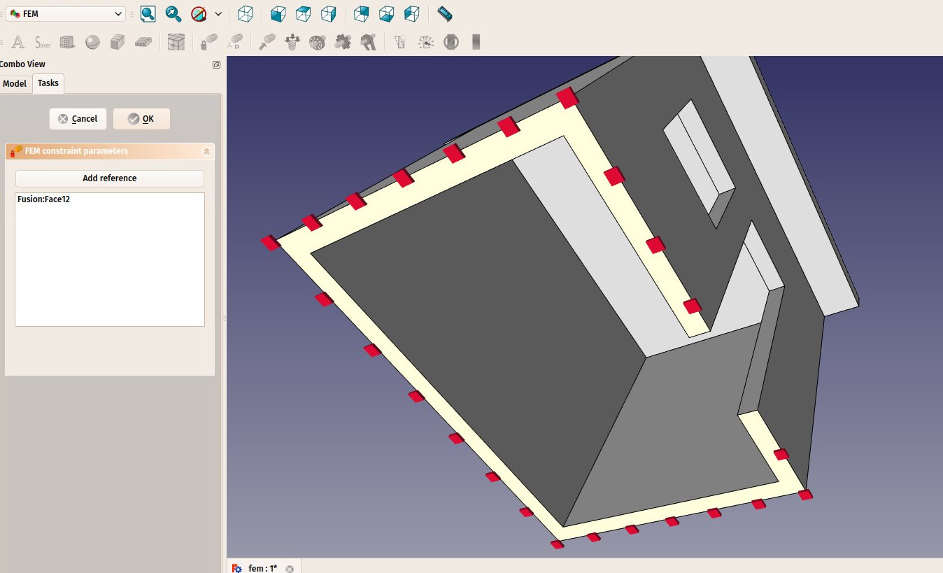
- We are now ready to apply forces. Let's start by specifying which faces are fixed into the ground and can therefore not move. Press the File:Fem ConstraintFixed.png Constraint fixed button.
- Click on the bottom face of our building and press OK. The bottom face is now indicated as unmovable:
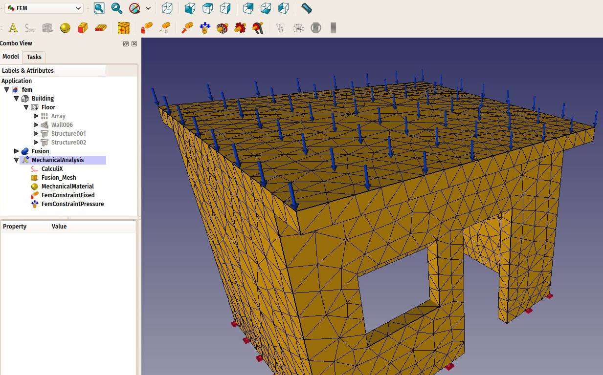
- We will now add a load on the top face, that could represent, for example, a massive weight being spread on the roof. For this we will use a pressure constraint. Press the File:Fem ConstraintPressure.png Constraint pressure button.
- Click the top face of the roof, set the pressure to 10MPa (the pressure is applied by square millimeter) and click the OK button. Our force is now applied:
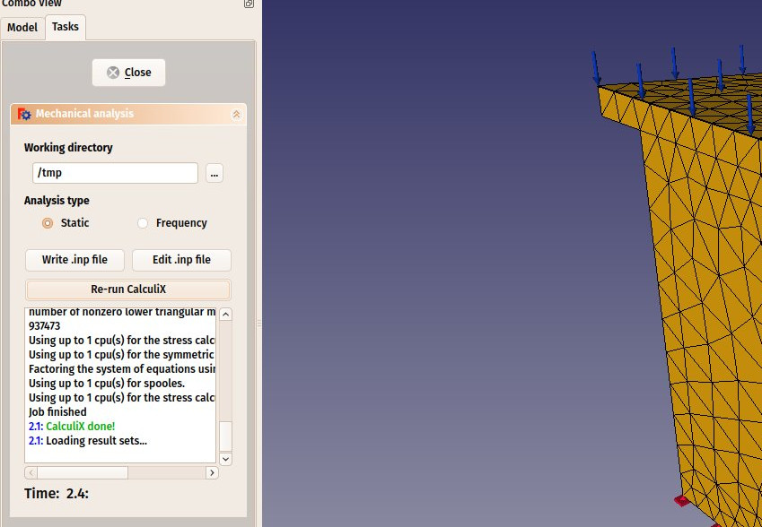
- We are now ready to start the calculation. Select the CalculiX object in the tree view, and press the File:Fem ControlSolver.png Start Calculation button.
- In the task panel that will open, click first the Write .inp file button to create the input file for CalculiX, then the Run CalculiX button. A few moments later, the calculation will be done:
- We can now look at the results. Close the task panel, and see that a new Results object has been added to our analysis.
- Double-click the Results object
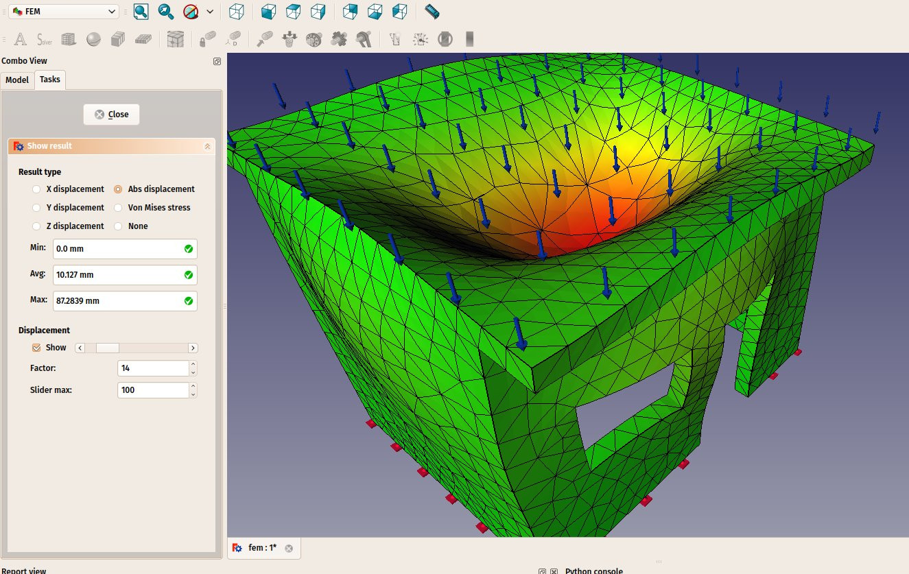
- Set the type of result that you want to see on the mesh, for example "absolute displacement", tick the show checkbox under Displacement, and move the slider next to it. You will be able to see the deformation growing as you apply more force:
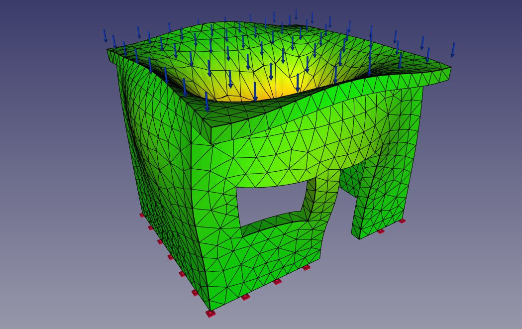
The results displayed by the FEM workbench are of course currently not enough to perform real-life decisions about structures dimensioning and materials. However, they can already give precious information about how the forces flow through a structure, and which are the weak areas that will bear the more stress.
Загрузки
- Файл, созданный в процессе работы: https://github.com/yorikvanhavre/FreeCAD-manual/blob/master/files/fem.FCStd
Читать далее
