Macro Draft Circle 3 Points/fr: Difference between revisions
m (minor) |
No edit summary |
||
| (26 intermediate revisions by 4 users not shown) | |||
| Line 1: | Line 1: | ||
<languages/> |
|||
{{Macro/fr|Icon=Macro_Draft_Circle_3_Points|Name=Macro_Draft_Circle_3_Points|Name/fr=Macro_Draft_Circle_3_Points|Description=Crée un cercle à partir de 3 points sélectionnés.|Author=Mario52}} |
|||
{{Macro/fr |
|||
|Name=Macro Make Circle 3 Points |
|||
|Icon=Macro_Make_Circle_3_Points.png |
|||
|Description=Crée un cercle à partir de 3 points ou trois objets sélectionnés. |
|||
|Author=Mario52 |
|||
|Version=01.00 |
|||
|Date=2013-03-11 |
|||
|FCVersion=All |
|||
|Download=[https://www.freecadweb.org/wiki/images/c/c7/Macro_Make_Circle_3_Points.png ToolBar Icon] |
|||
}} |
|||
==Description== |
==Description== |
||
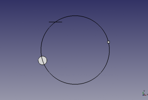
Cette macro crée un cercle sur 3 points. Si trois objets sont sélectionnés le centre de ces formes seront les points du cercle. |
|||
| ⚫ | |||
{{Caption|Circle built on 3 selected points}} |
|||
Cette macro crée un cercle circonscrit orthogonal sur 3 points sélectionnés. Les points peuvent être des objets comme des cubes, cylindres, . . . les coordonnées alors retenues seront le centre de ces formes. |
|||
<br><br> |
|||
| ⚫ | |||
| ⚫ | |||
==Utilisation== |
==Utilisation== |
||
| ⚫ | |||
| ⚫ | |||
Si la forme est une ligne, la coordonnée sera le centre de la ligne. |
|||
==Options== |
==Options== |
||
| ⚫ | |||
| ⚫ | |||
| ⚫ | |||
| ⚫ | |||
ToolBar Icon [[Image:Macro_Make_Circle_3_Points.png]] |
|||
| ⚫ | |||
| ⚫ | |||
Draft_Circle_3_Points.FCMacro |
'''Draft_Circle_3_Points.FCMacro''' |
||
{{MacroCode|code= |
|||
<pre> |
|||
# -*- coding: utf-8 -*- |
# -*- coding: utf-8 -*- |
||
# créer un cercle à partir de 3 points sélectionnés sur le plan X,Y |
# créer un cercle à partir de 3 points sélectionnés sur le plan X,Y |
||
| Line 88: | Line 96: | ||
FreeCAD.Console.PrintError("Sélectionnez 3 points et recommencez\r\n") |
FreeCAD.Console.PrintError("Sélectionnez 3 points et recommencez\r\n") |
||
}} |
|||
</pre> |
|||
| ⚫ | |||
| ⚫ | |||
En plus des |
En plus des fonctionnalités précédentes, cet exemple est utilisé pour aligner un cercle orthogonal sur chaque forme dans la sélection, et le plan «XY, YZ, XZ» choisi. <br /> |
||
| ⚫ | |||
| ⚫ | |||
<center> |
<center> |
||
<gallery widths="200" heights="100"> |
<gallery widths="200" heights="100"> |
||
| Line 103: | Line 111: | ||
</gallery> |
</gallery> |
||
</center> |
</center> |
||
<br> |
|||
{{clear}} |
{{clear}} |
||
The settings to change. |
|||
Les paramètres à modifier. |
|||
<pre> |
|||
{{MacroCode|code= |
|||
# Modifier les valeurs ci dessous |
|||
# Change the values here below |
|||
# |
# mode by default vueChoix = 0 and alignerSur = 0 |
||
vueChoix=0 # |
vueChoix=0 # choice of the top view = 1 XY, view Front = 2 ZX, Right view = 3 ZY |
||
alignerSur=0 # |
alignerSur=0 # Aligns the circle shaped the choice (1,2 or 3) or Z = 0 |
||
afficherPoint=1 # |
afficherPoint=1 # Displays the center point of the circle |
||
</pre> |
|||
}} |
|||
<br> |
|||
<pre> |
|||
{{MacroCode|code= |
|||
# -*- coding: utf-8 -*- |
# -*- coding: utf-8 -*- |
||
# créer un cercle à partir de 3 points séléctionnés |
# créer un cercle à partir de 3 points séléctionnés |
||
| Line 120: | Line 129: | ||
# à la coordonnée d'une des trois formes sélectionnées au choix |
# à la coordonnée d'une des trois formes sélectionnées au choix |
||
# et création du point central O/N |
# et création du point central O/N |
||
# 04/03/2013 |
# 04/03/2013 , 07/09/2018 replace PyQt4 to PySide |
||
# la formule provient de |
# la formule provient de |
||
# http://www-obs.univ-lyon1.fr/labo/fc/Ateliers_archives/ateliers_2005-06/cercle_3pts.pdf |
# http://www-obs.univ-lyon1.fr/labo/fc/Ateliers_archives/ateliers_2005-06/cercle_3pts.pdf |
||
| Line 129: | Line 138: | ||
from math import sqrt, pi, sin, cos |
from math import sqrt, pi, sin, cos |
||
from FreeCAD import Base |
from FreeCAD import Base |
||
from |
from PySide import QtCore, QtGui |
||
def errorDialog(msg): |
def errorDialog(msg): |
||
| Line 144: | Line 153: | ||
if afficherPoint==1: |
if afficherPoint==1: |
||
Draft.makePoint(x,y,z) |
Draft.makePoint(x,y,z) |
||
diag = QtGui.QMessageBox(QtGui.QMessageBox.Information,u" |
diag = QtGui.QMessageBox(QtGui.QMessageBox.Information,u"Coordinates",u"Coordinates X : "+str(x)+"\r\n"+u"Coordinates Y : "+str(y)+"\n"+u"Coordinates Z : "+str(z)+"\nRayon\t : "+str(rayon)) |
||
diag.setWindowModality(QtCore.Qt.ApplicationModal) |
diag.setWindowModality(QtCore.Qt.ApplicationModal) |
||
diag.exec_() |
diag.exec_() |
||
| Line 163: | Line 172: | ||
ta[i+2]=(x.z) |
ta[i+2]=(x.z) |
||
i=i+3 |
i=i+3 |
||
# Change the values here below |
|||
# Modifier les valeurs ci dessous |
|||
# mode by default vueChoix = 0 and alignerSur = 0 |
|||
vueChoix=0 |
vueChoix=0 # choice of the top view = 1 XY, view Front = 2 ZX, Right view = 3 ZY |
||
alignerSur=0 # |
alignerSur=0 # Aligns the circle shaped the choice (1,2 or 3) or Z = 0 |
||
afficherPoint=1 # |
afficherPoint=1 # Displays the center point of the circle |
||
# Affectation des variables |
# Affectation des variables |
||
if vueChoix==3: # |
if vueChoix==3: # View of right ZY (Red) |
||
z_point_1=ta[0] |
z_point_1=ta[0] |
||
x_point_1=ta[1] |
x_point_1=ta[1] |
||
| Line 183: | Line 192: | ||
y_point_3=ta[8] |
y_point_3=ta[8] |
||
elif vueChoix==2: # |
elif vueChoix==2: # Front view ZX (Green) |
||
y_point_1=ta[0] |
y_point_1=ta[0] |
||
z_point_1=ta[1] |
z_point_1=ta[1] |
||
| Line 196: | Line 205: | ||
x_point_3=ta[8] |
x_point_3=ta[8] |
||
else: # |
else: # Top view XY (blue) |
||
x_point_1=ta[0] |
x_point_1=ta[0] |
||
y_point_1=ta[1] |
y_point_1=ta[1] |
||
| Line 209: | Line 218: | ||
z_point_3=ta[8] |
z_point_3=ta[8] |
||
# Calculation of coordinates of the center of the circle |
|||
# Calcul des coordonnées du centre du cercle |
|||
try: |
try: |
||
centreX =((x_point_3**2-x_point_2**2+y_point_3**2-y_point_2**2)/(2*(y_point_3-y_point_2))-(x_point_2**2-x_point_1**2+y_point_2**2-y_point_1**2)/(2*(y_point_2-y_point_1)))/((x_point_3-x_point_2)/(y_point_3-y_point_2)-(x_point_2-x_point_1)/(y_point_2-y_point_1)) |
centreX =((x_point_3**2-x_point_2**2+y_point_3**2-y_point_2**2)/(2*(y_point_3-y_point_2))-(x_point_2**2-x_point_1**2+y_point_2**2-y_point_1**2)/(2*(y_point_2-y_point_1)))/((x_point_3-x_point_2)/(y_point_3-y_point_2)-(x_point_2-x_point_1)/(y_point_2-y_point_1)) |
||
| Line 215: | Line 224: | ||
rayon =sqrt((x_point_1-centreX)**2+(y_point_1-centreY)**2) |
rayon =sqrt((x_point_1-centreX)**2+(y_point_1-centreY)**2) |
||
except: |
except: |
||
errorDialog(u" |
errorDialog(u"Impossible calculation too aligned elements") |
||
else: |
else: |
||
#finally: sera TOUJOURS exécuté |
#finally: sera TOUJOURS exécuté |
||
# |
# Definition of the coordinate Z |
||
centreZ=0 |
centreZ=0 |
||
# Création du cercle |
# Création du cercle |
||
pl=FreeCAD.Placement() |
pl=FreeCAD.Placement() |
||
if vueChoix==1: # Plan XY Dessus |
if vueChoix==1: # Plan XY Dessus |
||
pl.Rotation.Q=(0,0,0,1.0) |
pl.Rotation.Q=(0,0,0,1.0) |
||
if alignerSur==1: |
if alignerSur==1: |
||
| Line 230: | Line 239: | ||
elif alignerSur==3: |
elif alignerSur==3: |
||
affiche(centreX,centreY,z_point_3,rayon,0.0,0.0,1.0,afficherPoint) |
affiche(centreX,centreY,z_point_3,rayon,0.0,0.0,1.0,afficherPoint) |
||
elif vueChoix==2: |
elif vueChoix==2: # Plan XZ Face |
||
pl.Rotation.Q=(1,0,0,1.0) |
pl.Rotation.Q=(1,0,0,1.0) |
||
if alignerSur==1: |
if alignerSur==1: |
||
| Line 238: | Line 247: | ||
elif alignerSur==3: |
elif alignerSur==3: |
||
affiche(centreY,z_point_3,centreX,rayon,0.0,1.0,0.0,afficherPoint) |
affiche(centreY,z_point_3,centreX,rayon,0.0,1.0,0.0,afficherPoint) |
||
elif vueChoix==3: |
elif vueChoix==3: # Plan YZ Droite |
||
pl.Rotation.Q=(0,1,0,1.0) |
pl.Rotation.Q=(0,1,0,1.0) |
||
if alignerSur==1: |
if alignerSur==1: |
||
| Line 257: | Line 266: | ||
else: |
else: |
||
# Si la condition n'est pas remplie, recommencer |
# Si la condition n'est pas remplie, recommencer |
||
errorDialog(u" |
errorDialog(u"Select 3 points and repeat") |
||
#FreeCAD.Console.PrintError(" |
#FreeCAD.Console.PrintError("Select 3 points and repeatr\n") |
||
}} |
|||
</pre> |
|||
== |
==Anaglyphe== |
||
Voici une vue Anaglyphe qui vous permet de voir deux positions différentes de la vue en utilisant des lunettes avec des filtres rouges et Cyan [[Image:Anaglyph_Tango.png|24px]].<br /> |
|||
Regardez en alternance avec l'oeil gauche et l'oeil droit pour voir les vues séparément. |
|||
| ⚫ | |||
<center> |
|||
| ⚫ | |||
[[File:Cercle3Points2D_anaglyphe.png|480px|Anaglyphe]] |
|||
</center> |
|||
| ⚫ | |||
==Credits== |
|||
<br> |
|||
| ⚫ | |||
{{languages/fr | {{en|Macro_Draft_Circle_3_Points}} {{it|Macro_Draft_Circle_3_Points/it}} }} |
|||
| ⚫ | |||
Latest revision as of 13:28, 23 May 2020
| Description |
|---|
| Crée un cercle à partir de 3 points ou trois objets sélectionnés. Version macro : 01.00 Date dernière modification : 2013-03-11 Version FreeCAD : All Téléchargement : ToolBar Icon Auteur: Mario52 |
| Auteur |
| Mario52 |
| Téléchargement |
| ToolBar Icon |
| Liens |
| Page des macros Comment installer une macro Comment créer une barre d'outils |
| Version Macro |
| 01.00 |
| Dernière modification |
| 2013-03-11 |
| Version(s) FreeCAD |
| All |
| Raccourci clavier |
| None |
| Voir aussi |
| None |
Description
Cette macro crée un cercle sur 3 points. Si trois objets sont sélectionnés le centre de ces formes seront les points du cercle.
Circle built on 3 selected points
Utilisation
Sélectionnez 3 points, ou formes dans la vue 3D et lancez la macro.
Si le forme est une ligne, le point sera le centre de la ligne.
Options
Si l'objet sélectionné a différents plans, (xy Z10, xy Z2, xy Z5) le cercle est construit aux coordonnées x,y Z=0.
Si tous le objets sélectionnés ont la même hauteur Z ex: (xy Z5, xy Z5, xy Z5), le ercle est construit sur le pla x,y Z=5.
Script
Draft_Circle_3_Points.FCMacro
# -*- coding: utf-8 -*-
# créer un cercle à partir de 3 points sélectionnés sur le plan X,Y
# 04/03/2013
# la formule provient de
# http://www-obs.univ-lyon1.fr/labo/fc/Ateliers_archives/ateliers_2005-06/cercle_3pts.pdf
# lire la note dans le pdf, sur l'ordre de sélection des points,
# si la formule renvoie une erreur (exemple les 3 points dans le même alignement)
#
import Draft, Part, FreeCAD, math, PartGui, FreeCADGui
from math import sqrt, pi, sin, cos
from FreeCAD import Base

# prendre les objets sélectionnés
sel = FreeCADGui.Selection.getSelection()
i=0
centreX=0
centreY=0
rayon=0
# S'il y a 3 points sélectionnés alors..
if len(sel)==3 :
	i=0
	ta=[0,0,0,0,0,0,0,0,0]
	for obj in sel:
		x=(obj.Shape.BoundBox.Center)
		ta[i+0]=(x.x)
		ta[i+1]=(x.y)
		ta[i+2]=(x.z)
		i=i+3
# Affectation des variables
	x_point_1=ta[0]
	y_point_1=ta[1]
	z_point_1=ta[2]

	x_point_2=ta[3]
	y_point_2=ta[4]
	z_point_2=ta[5]

	x_point_3=ta[6]
	y_point_3=ta[7]
	z_point_3=ta[8]
# Calcul des coordonnées du centre du cercle
	centreX =((x_point_3**2-x_point_2**2+y_point_3**2-y_point_2**2)/(2*(y_point_3-y_point_2))-(x_point_2**2-x_point_1**2+y_point_2**2-y_point_1**2)/(2*(y_point_2-y_point_1)))/((x_point_3-x_point_2)/(y_point_3-y_point_2)-(x_point_2-x_point_1)/(y_point_2-y_point_1))
	centreY =-(x_point_2-x_point_1)/(y_point_2-y_point_1)*centreX+(x_point_2**2-x_point_1**2+y_point_2**2-y_point_1**2)/(2*(y_point_2-y_point_1))
	rayon =sqrt((x_point_1-centreX)**2+(y_point_1-centreY)**2)
# Définition de la coordonnée Z
# Si toutes les coordonnées Z sont égales le centreZ s'aligne à la coordonnée Z
	if z_point_1==z_point_2 and z_point_2==z_point_3:
		centreZ=z_point_1
	else:
# Si une coordonnée est différente alors Z=0
		centreZ=0
# Création du cercle
	pl=FreeCAD.Placement()
	pl.Rotation.Q=(0.0,-0.0,-0.0,1.0)
	pl.Base=FreeCAD.Vector(centreX,centreY,centreZ)
	Draft.makeCircle((rayon),placement=pl,face=False,support=None)
# Affiche le résultat dans la Vue rapport de FreeCAD
	FreeCAD.Console.PrintMessage("Coordonnée X : "+str(centreX)+"\r\n")
	FreeCAD.Console.PrintMessage("Coordonnée Y : "+str(centreY)+"\r\n")
	FreeCAD.Console.PrintMessage("Coordonnée Z : "+str(centreZ)+"\r\n")
	FreeCAD.Console.PrintMessage("Rayon        : "+str(rayon  )+"\r\n")
else:
# Si la condition n'est pas remplie, recommencer
	FreeCAD.Console.PrintError("Sélectionnez 3 points et recommencez\r\n")
Version améliorée
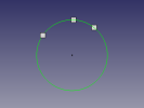
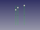
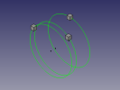
En plus des fonctionnalités précédentes, cet exemple est utilisé pour aligner un cercle orthogonal sur chaque forme dans la sélection, et le plan «XY, YZ, XZ» choisi.
Le cercle prend la couleur de l'axe dédié indépendamment de la couleur actuelle, et le point central du cercle est dessiné (option O/N).
-
Cercle circonscrit sur 3 formes,
-
de manière orthogonale sur la forme choisie
-
-
The settings to change.
# Change the values here below
			# mode by default vueChoix = 0 and alignerSur = 0
	vueChoix=0	# choice of the top view = 1 XY, view Front = 2 ZX, Right view = 3 ZY
	alignerSur=0	# Aligns the circle shaped the choice (1,2 or 3) or Z = 0
	afficherPoint=1	# Displays the center point of the circle
# -*- coding: utf-8 -*-
# créer un cercle à partir de 3 points séléctionnés
# avec comme options le cercle peut être construit sur un plans au choix
# à la coordonnée d'une des trois formes sélectionnées au choix
# et création du point central O/N
# 04/03/2013 , 07/09/2018 replace PyQt4 to PySide
# la formule provient de
# http://www-obs.univ-lyon1.fr/labo/fc/Ateliers_archives/ateliers_2005-06/cercle_3pts.pdf
# lire la note dans le pdf, sur l'ordre de sélection des points,
# si la formule renvoie une erreur (exemple les 3 points dans le même alignement)
#
import Draft, Part, FreeCAD, math, PartGui, FreeCADGui
from math import sqrt, pi, sin, cos
from FreeCAD import Base
from PySide import QtCore, QtGui

def errorDialog(msg):
    # Create a simple dialog QMessageBox
    # The first argument indicates the icon used: one of QtGui.QMessageBox.{NoIcon, Information, Warning, Critical, Question}
	diag = QtGui.QMessageBox(QtGui.QMessageBox.Critical,u"Error Message",msg)
	diag.setWindowModality(QtCore.Qt.ApplicationModal)
	diag.exec_()

def affiche(x,y,z,rayon,r,v,b,afficherPoint):
	pl.Base=FreeCAD.Vector(x,y,z)
	Draft.makeCircle((rayon),placement=pl,face=False,support=None)
	FreeCADGui.activeDocument().activeObject().LineColor = (r,v,b)
	if afficherPoint==1:
		Draft.makePoint(x,y,z)
	diag = QtGui.QMessageBox(QtGui.QMessageBox.Information,u"Coordinates",u"Coordinates X : "+str(x)+"\r\n"+u"Coordinates Y : "+str(y)+"\n"+u"Coordinates Z : "+str(z)+"\nRayon\t     : "+str(rayon))
	diag.setWindowModality(QtCore.Qt.ApplicationModal)
	diag.exec_()

# prendre les objets selectionnes
sel = FreeCADGui.Selection.getSelection()
i=0
centreX=0;centreY=0;rayon=0

# S'il y a 3 points sélectionnés alors..
if len(sel)==3 :
	i=0
	ta=[0,0,0,0,0,0,0,0,0]
	for obj in sel:
		x=(obj.Shape.BoundBox.Center)
		ta[i+0]=(x.x)
		ta[i+1]=(x.y)
		ta[i+2]=(x.z)
		i=i+3
# Change the values here below
			# mode by default vueChoix = 0 and alignerSur = 0
	vueChoix=0	# choice of the top view = 1 XY, view Front = 2 ZX, Right view = 3 ZY
	alignerSur=0	# Aligns the circle shaped the choice (1,2 or 3) or Z = 0
	afficherPoint=1	# Displays the center point of the circle

    # Affectation des variables
	if vueChoix==3:		# View of right ZY (Red)
 	  	z_point_1=ta[0]
		x_point_1=ta[1]
		y_point_1=ta[2]

		z_point_2=ta[3]
		x_point_2=ta[4]
		y_point_2=ta[5]

		z_point_3=ta[6]
		x_point_3=ta[7]
		y_point_3=ta[8]

	elif vueChoix==2:	# Front view ZX (Green)
 	  	y_point_1=ta[0]
		z_point_1=ta[1]
		x_point_1=ta[2]

		y_point_2=ta[3]
		z_point_2=ta[4]
		x_point_2=ta[5]

		y_point_3=ta[6]
		z_point_3=ta[7]
		x_point_3=ta[8]

	else:			# Top view XY (blue)
 	  	x_point_1=ta[0]
		y_point_1=ta[1]
		z_point_1=ta[2]

		x_point_2=ta[3]
		y_point_2=ta[4]
		z_point_2=ta[5]

		x_point_3=ta[6]
		y_point_3=ta[7]
		z_point_3=ta[8]

    # Calculation of coordinates of the center of the circle
	try:
		centreX =((x_point_3**2-x_point_2**2+y_point_3**2-y_point_2**2)/(2*(y_point_3-y_point_2))-(x_point_2**2-x_point_1**2+y_point_2**2-y_point_1**2)/(2*(y_point_2-y_point_1)))/((x_point_3-x_point_2)/(y_point_3-y_point_2)-(x_point_2-x_point_1)/(y_point_2-y_point_1))
		centreY =-(x_point_2-x_point_1)/(y_point_2-y_point_1)*centreX+(x_point_2**2-x_point_1**2+y_point_2**2-y_point_1**2)/(2*(y_point_2-y_point_1))
		rayon =sqrt((x_point_1-centreX)**2+(y_point_1-centreY)**2)
	except:
		errorDialog(u"Impossible calculation too aligned elements")
	else:
	#finally: sera TOUJOURS exécuté
	   # Definition of the coordinate Z
		centreZ=0
	    # Création du cercle
		pl=FreeCAD.Placement()
		if vueChoix==1:	# Plan XY Dessus
			pl.Rotation.Q=(0,0,0,1.0)
			if alignerSur==1:
				affiche(centreX,centreY,z_point_1,rayon,0.0,0.0,1.0,afficherPoint)
			elif alignerSur==2:
				affiche(centreX,centreY,z_point_2,rayon,0.0,0.0,1.0,afficherPoint)
			elif alignerSur==3:
				affiche(centreX,centreY,z_point_3,rayon,0.0,0.0,1.0,afficherPoint)
		elif vueChoix==2: # Plan XZ Face
			pl.Rotation.Q=(1,0,0,1.0)
			if alignerSur==1:
				affiche(centreY,z_point_1,centreX,rayon,0.0,1.0,0.0,afficherPoint)
			elif alignerSur==2:
				affiche(centreY,z_point_2,centreX,rayon,0.0,1.0,0.0,afficherPoint)
			elif alignerSur==3:
				affiche(centreY,z_point_3,centreX,rayon,0.0,1.0,0.0,afficherPoint)
		elif vueChoix==3: # Plan YZ Droite
			pl.Rotation.Q=(0,1,0,1.0)
			if alignerSur==1:
				affiche(z_point_1,centreX,centreY,rayon,1.0,0.0,0.0,afficherPoint)
			elif alignerSur==2:
				affiche(z_point_2,centreX,centreY,rayon,1.0,0.0,0.0,afficherPoint)
			elif alignerSur==3:
				affiche(z_point_3,centreX,centreY,rayon,1.0,0.0,0.0,afficherPoint)
		else:	# modifier pour avoir XYZ
			# si les coordonnées Z sont égales alors le cercle s'aligne à Z
			if z_point_1==z_point_2 and z_point_2==z_point_3:
				centreZ=z_point_1
				affiche(centreX,centreY,z_point_1,rayon,0.0,0.0,0.0,afficherPoint)
			else:
	        	# Si une coordonnée est différente alors Z=0
				affiche(centreX,centreY,0,rayon,0.0,0.0,0.0,afficherPoint)

else:
    # Si la condition n'est pas remplie, recommencer
	errorDialog(u"Select 3 points and repeat")
	#FreeCAD.Console.PrintError("Select 3 points and repeatr\n")
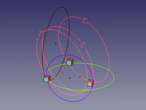
Anaglyphe
Voici une vue Anaglyphe qui vous permet de voir deux positions différentes de la vue en utilisant des lunettes avec des filtres rouges et Cyan ![]() .
.
Regardez en alternance avec l'oeil gauche et l'oeil droit pour voir les vues séparément.
Credits
La genèse de la macro Draft Circle 3 Points on the forum (PYTHON) coordonnées d'un point avec l'aide flachyjoe merci.
La formule vient de cercle_3pts.pdf et utilisée avec l'aimable permission de son auteur.
