Por onde começar
Novidades
- Notas de lançamento da versão 0.12 : Veja o que há de novo na versão 0.12 do FreeCAD
- Notas de lançamento da versão 0.13 : Veja o que há de novo na versão 0.13 do FreeCAD
- Notas de lançamento da versão 0.14 : Veja o que há de novo na versão 0.14 do FreeCAD
- Notas de lançamento da versão 0.15 : Veja o que há de novo na versão 0.15 do FreeCAD
Introdução
O FreeCAD é uma aplicação de modelação paramétrica CAD/CAE. Ainda está na fase de desenvolvimento inicial, por isso não espere poder produzir trabalho com ele. Mas, se está curioso acerca da sua funcionalidade e das funcionalidades em desenvolvimento, esteja à vontade para o instalar e para o experimentar. Neste momento, já há muita funcionalidade implementada, mas ainda não fui desenvolvido o interface para ela. Isto quer dizer que se souber um pouco de Python, será capaz de produzir e modificar geometria complexa facilmente. Se não, irá provavelmente achar que o FreeCAd ainda tem pouco para lhe oferecer. Mas tenha paciência, a situação deverá mudar em breve.
E se depois de testar o FreeCAD tiver ideias ou opiniões, por favor partilhe connosco no forum!
O FreeCAD é uma aplicação de modelação paramétrica 3D CAD/CAE . É primeiramente feita para desenho mecânico, mas também serve todos os outros usos onde seja necessário modelar objetos 3D com precisão e controlo sobre o processo/historial de modelação.
O FreeCAD continua numa fase inicial de desenvolvimento, pelo que, apesar de já oferecer uma larga lista (que continua a crescer) de funcionalidades, muito continua a faltar, especialmente quando comparado com soluções comerciais, pelo que pode não ser considerado suficientemente desenvolvido para utilização em ambiente de produção. Ainda assim, existe uma comunidade em rápido crescimento de utilizadores entusiastas, e podem ser já encontrados muitos exemplos de projetos de qualidade desenvolvidos com o FreeCAD.
Tal como todos os projetos "open-source", O projeto FreeCAD não é um trabalho entregue pelos desenvolvedores em sentido único. Ele depende muito da sua comunidade para crescer, ganhar funcionalidades, e estabilidade (corrigir de bugs). Por isso convém não esquecer, quando começar a usar o FreeCAD, se gostar de trabalhar com ele, pode influenciar diretamente e ajudar o projeto!
Instalação
Antes de mais faça o download e instale o FreeCAD (se ainda não o fez). Veja a página Download/pt para informações acerca das versões mais recentes e atualizações. Há pacotes de instalação preparados para o Windows, Ubuntu/Debian (.deb) OpenSUSE (.rpm) e Mac OSX.
First of all (if not done already) download and install FreeCAD. See the Download page for information about current versions and updates, and the Installing page for information about how to install FreeCAD. There are install packages ready for Windows (.msi), Ubuntu & Debian (.deb) openSUSE (.rpm) and Mac OSX. As FreeCAD is open-source, if you are adventurous, but want to have a look at the brand-new features being developed right now, you can also grab the source code and compile FreeCAD yourself.
Explorando o FreeCAD

O FreeCAD é uma ferramenta de modelação 3D genérica, centrada na engenharia mecânica e áreas relacionadas, assim como outras especialidades da engenharia ou da arquitetura. Foi concebido como uma plataforma para desenvolver qualquer tipo de aplicação 3D, mas também para fazer tarefas muito específicas. Para esse fim, o seu interface está dividido em bancadas. As bancadas permitem o conteúdo do interface para mostrar todas as ferramentas ou apenas as necessárias para realizar uma determinada tarefa, ou grupo de tarefas.
O interface do FreeCAD pode portanto ser definido como um contentor muito simples, com um menu, uma vista 3D e alguns painéis laterais para mostrar os conteúdos de uma cena ou propriedades de objetos. Todos os conteúdos destes painéis pode ser mudada conforme a bancada.
Quando iniciar o FreeCAD pela primeira vez, ser-lhe-a apresentada um bancada "genérica", a que nós chamamos "bancada completa". Nesta bancada estão reunidas as ferramentas mais "maduras" de outras bancadas. Como o FreeCAD é muito novo e ainda não é usado para trabalho muito especializado, esta bancada é muito útil para explorar o FreeCAD facilmente. No fundo, todas as ferramentas suficientemente boas para produzir geometria estão aqui.
- The 3D view, showing the contents of your document
- The tree view, which shows the hierarchy and construction history of all the objects in your document
- The properties editor, which allows you to view and modify properties of the selected object(s)
- The output window, which is where FreeCAD prints messages, warnings and errors
- The python console, where all the commands executed by FreeCAD are printed, and where you can enter python code
- The workbench selector, where you select the active workbench
The main concept behind the FreeCAD interface is that it is separated into workbenches. A workbench is a collection of tools suited for a specific task, such as working with meshes, or drawing 2D objects, or constrained sketches. You can switch the current workbench with the workbench selector (6). You can customize the tools included in each workbench, add tools from other workbenches or even self-created tools, that we call macros. There is also a generic workbench which gathers the most commonly used tools from other workbenches, called the complete workbench.
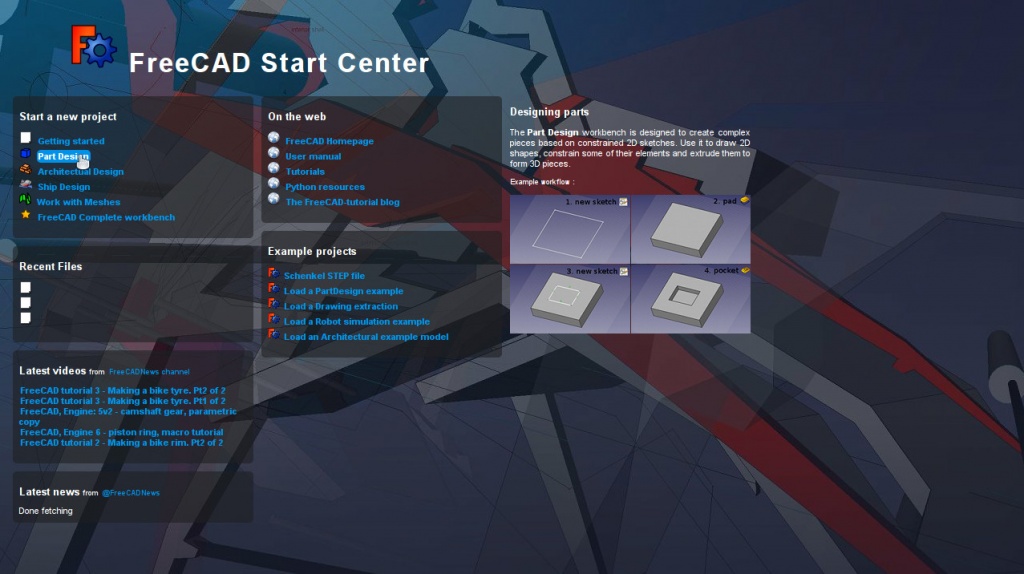
When you start FreeCAD for the first time, you are presented with the start center:

The Start Center allows you to quickly jump to one of the most common workbenches, open one of the recent files, or see the latest news from the FreeCAD world. You can change the default workbench in the preferences.
Orientação no espaço 3D
O FreeCAD tem tres modos de orientação diferentes, que podem ser definidos na caixa das preferências ou mudadas clicando com o botão direito na janela 3D. Os detalhes completos estão na página Modos do rato. No modo por defeito ("Navegação CAD"), os comandos são os seguintes
| Select | Pan | Zoom | Rotate View | Rotate View
Alternate Method |
|---|---|---|---|---|

|

|

|

|

|
| Press the left mouse button over an object you want to select. Holding down ctrl allows the selection of multiple objects. | Click the middle mouse button and move the object around to pan | Use the mouse wheel to zoom in and out. | Click first with the middle mouse button, hold it down, and then click the left mouse button and drag the mouse in the desired direction. The cursor location at the middle mouse button click determines the center of rotation. Rotation works like spinning a ball which rotates around its center. If the buttons are released before you stop the mouse motion, the object continues spinning, if this is enabled. A double click with the middle mouse button sets a new center of rotation. | Click first with the middle mouse button, hold it down, and then click the right mouse button and drag the mouse in the desired direction. This method works just like the previously described Rotate View that uses Middle Mouse Button + Left Mouse Button, except that the middle mouse button may be released after the right mouse button is pressed. Users who use the mouse with their right hand may find this Rotate View method easier than the previous method. |

|

|

|
||
| Press and hold Ctrl key and click and release right mouse button to pan (rev 0.14) | Once in Pan mode, press and release left mouse button to Zoom, to exit back to pan mode press and release right mouse button (rev 0.14) | Once in Pan mode, click and momentary hold left mouse button to rotate, to exit back to pan mode press and release right mouse button (rev 0.14) |
Há também várias pré-definições para as vistas (vista de cima, de frente, etc) disponíveis no menu Vista e na barrsa de ferramentas Vista, e através de atalhos do teclado (1, 2, etc...)
 desenho 2D
 Creating 3D Parts
Exporting to 2D Drawings
FreeCAD has four different navigation modes available, that change the way you use your mouse to interact with the objects in the 3D view and the view itself. One of them is specifically made for touchpads, where the middle mouse button is not used. The following table describes the default mode, called CAD Navigation (You can quickly change the current navigation mode by right-clicking on an empty area of the 3D view):
You also have several view presets (top view, front view, etc) available in the View menu and on the View toolbar, and by numeric shortcuts (1, 2, etc...), and by right-clicking on an object or on an empty area of the 3D view, you have quick access to some common operations, such as setting a particular view, or locating an object in the Tree view.
First steps with FreeCAD
FreeCAD's focus is to allow you to make high-precision 3D models, to keep tight control over those models (being able to go back into modelling history and change parameters), and eventually to build those models (via 3D printing, CNC machining or even construction worksite). It is therefore very different from some other 3D applications made for other purposes, such as animation film or gaming. Its learning curve can be steep, specially if this is your first contact with 3D modeling. If you are struck at some point, don't forget that the friendly community of users on the FreeCAD forum might be able to get you out in no time.
The workbench you will start using in FreeCAD depends on the type of job you need to do: If you are going to work on mechanical models, or more generally any small-scale objects, you'll probably want to try the PartDesign Workbench. If you will work in 2D, then switch to the Draft Workbench, or the Sketcher Workbench if you need constraints. If you want to do BIM, launch the Arch Workbench. If you are working with ship design, there is a special Ship Workbench for you. And if you come from the OpenSCAD world, try the OpenSCAD Workbench.
You can switch workbenches at any time, and also customize your favorite workbench to add tools from other workbenches.
Working with the PartDesign and Sketcher workbenches
The PartDesign Workbench is specially made to build complex objects, starting from simple shapes, and adding or removing pieces (that we call "features"), until you get to your final object. All the features you applied during the modelling process are stored in a separate view called the tree view, which also contains the other objects in your document. You can think of a PartDesign object as a succession of operations, each one applied to the result of the preceding one, forming one big chain. In the tree view, you see your final object, but you can expand it and retrieve all preceding states, and change any of their parameter, which automatically updates the final object.
The PartDesign workbench makes heavy use of another workbench, the Sketcher Workbench. The sketcher allows you to draw 2D shapes, which are defined by applying Constraints to the 2D shape. For example, you might draw a rectangle and set the size of a side by applying a length constraint to one of the sides. That side then cannot be resized anymore (unless the constraint is changed).
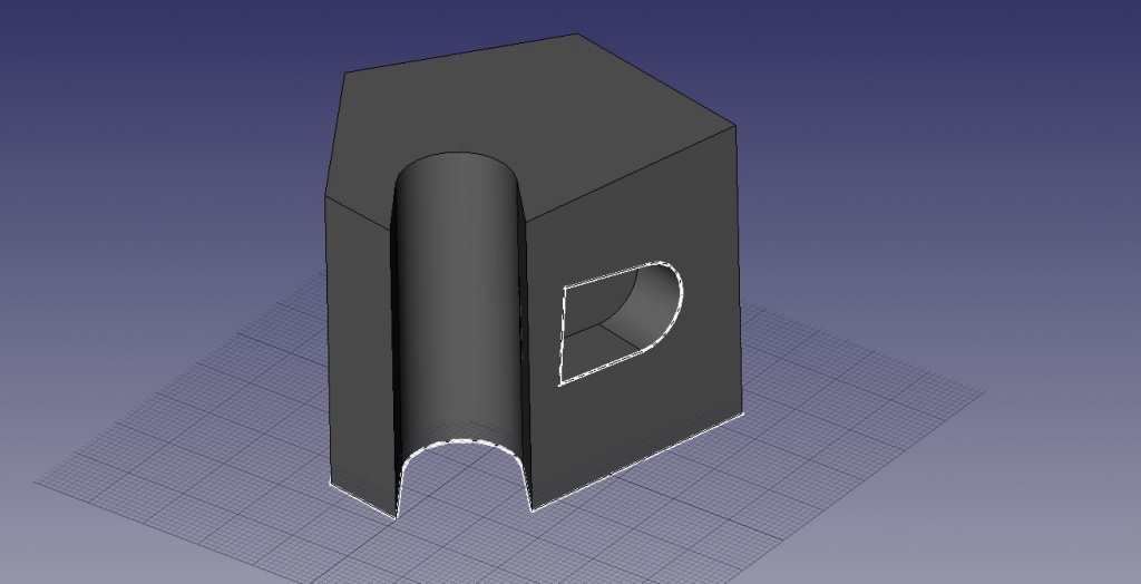
Those 2D shapes made with the sketcher are used a lot in the PartDesign workbench, for example to create 3D volumes, or to draw areas on the faces of your object that will then be hollowed from its main volume. This is a typical PartDesign workflow:
- Create a new sketch
- Draw a closed shape (make sure all points are joined)
- Close the sketch
- Expand the sketch into a 3D solid by using the pad tool
- Select one face of the solid
- Create a second sketch (this time it will be drawn on the selected face)
- Draw a closed shape
- Close the sketch
- Create a pocket from the second sketch, on the first object
Which gives you an object like this:

At any moment, you can select the original sketches and modify them, or change the extrusion parameters of the pad or pocket operations, which will update the final object.
Working with the Draft and Arch workbenches
The Draft Workbench and Arch Workbench behave a bit differently than the other workbenches above, although they follow the same rules, which are common to all of FreeCAD. In short, while the Sketcher and PartDesign are made primarily to design single pieces, Draft and Arch are made to ease your work when working with several, simpler objects.
The Draft Workbench offers you 2D tools a bit similar to what you can find in traditional 2D CAD applications such as AutoCAD. However, 2D drafting being far away from the scope of FreeCAD, don't expect to find there the full array of tools that these dedicated applications offer. Most of the Draft tools work not only in a 2D plane but also in the full 3D space, and benefit from special helper systems such as Work planes and object snapping.
The Arch Workbench adds BIM tools to FreeCAD, allowing you to build architectural models with parametric objects. The Arch workbench relies much on other modules such as Draft and Sketcher. All the Draft tools are also present in the Arch workbench, and most Arch tools make use of the Draft helper systems.
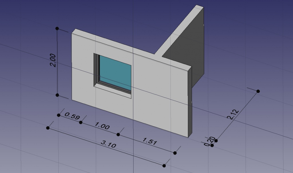
A typical workflow with Arch and Draft workbenches might be:
- Draw a couple of lines with the Draft Line tool
- Select each line and press the Wall tool to build a wall on each of them
- Join the walls by selecting them and pressing the Arch Add tool
- Create a floor object, and move your walls in it from the Tree view
- Create a building object, and move your floor in it from the Tree view
- Create a window by clicking the Window tool, select a preset in its panel, then click on a face of a wall
- Add dimensions by first setting the working plane if necessary, then using the Draft Dimension tool
Which will give you this:
More on the Tutorials page.
Scripting
And finally, one of the most powerful features of FreeCAD is the scripting environment. From the integrated python console (or from any other external Python script), you can gain access to almost any part of FreeCAD, create or modify geometry, modify the representation of those objects in the 3D scene or access and modify the FreeCAD interface. Python scripting can also be used in macros, which provide an easy method to create custom commands.


