Basic TechDraw Tutorial/fr: Difference between revisions
(Created page with "# Sélectionnez la Page dans la vue combinée et faites défiler jusqu'à la propriété Scale dans l'onglet Données. # Modifiez l'échelle de 1 à 2 et appuyez sur Entrée....") |
(Created page with "C'est mieux, mais un peu ennuyeux. Ajoutons quelques dimensions. # Sélectionnez (bouton gauche de la souris) le sommet supérieur gauche (petit point), puis sélectionnez ég...") |
||
| Line 35: | Line 35: | ||
[[Image:TDTut_TopView2to1.png|center]] |
[[Image:TDTut_TopView2to1.png|center]] |
||
C'est mieux, mais un peu ennuyeux. Ajoutons quelques dimensions. |
|||
Better, but a little boring. Let's add some Dimensions. |
|||
# Sélectionnez (bouton gauche de la souris) le sommet supérieur gauche (petit point), puis sélectionnez également (Ctrl+bouton gauche de la souris) sur le sommet inférieur gauche. |
|||
# Select (LMB) the top-left Vertex (small dot), then also select (Ctl-LMB) on the bottom-left vertex. |
|||
# |
# Cliquez sur [[Image:TechDraw_Dimension_Vertical.png|32px]] [[TechDraw_Dimension_Vertical/fr|Nouvelle cote verticale]]. Faites glisser le texte de cote hors du corps. |
||
# |
# Essayez à nouveau avec les sommets supérieur à gauche et supérieur droit et [[Image:TechDraw_Dimension_Horizontal.png|32px]] [[TechDraw_Dimension_Horizontal/fr|Nouvelle cote horizontale]]. |
||
[[Image:TDTut_TopView2Dims.png|center]] |
[[Image:TDTut_TopView2Dims.png|center]] |
||
Revision as of 16:48, 3 August 2018
| Thème |
|---|
| Dessin technique |
| Niveau |
| Débutant |
| Temps d'exécution estimé |
| Moins d'une heure |
| Auteurs |
| WandererFan |
| Version de FreeCAD |
| 0.17 ou ultérieur |
| Fichiers exemples |
| Basic Part Design for v0.17 Sample Basic TechDraw Tutorial Sample |
| Voir aussi |
| None |
Ce didacticiel présente au nouvel utilisateur certains des outils et techniques utilisés dans l' atelier de dessin technique TechDraw. Ce didacticiel n'est pas un guide complet de l'atelier TechDraw et de nombreux outils et fonctionnalités ne sont pas couverts. Ce didacticiel vous guidera dans les étapes nécessaires à la réalisation des dessins techniques de la pièce du Didacticiel d'introduction à l'atelier PartDesign.
Avant de commencer
Téléchargez le fichier d'exemple du didacticiel Part Design.
La tâche
Dans ce tutoriel, vous allez utiliser l'atelier TechDraw pour créer des dessins 2D de la pièce 3D ci-dessous. Nous allons créer plusieurs vues de la pièce et ajouter des dimensions clés. Ce didacticiel n'utilisera pas toutes les fonctionnalités et tous les outils disponibles dans l'atelier TechDraw, mais devrait suffire à donner à l'utilisateur de ce didacticiel les bases pour développer ses connaissances et ses compétences.
La pièce
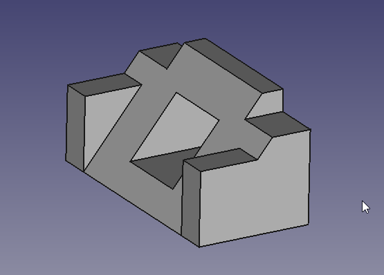
Créer un dessin
Démarrage
- Vous souhaiterez peut-être ajuster vos préférences avant de débuter. Voir la note 1.
- Ouvrez d'abord le fichier contenant notre pièce 3D. Ensuite, assurez-vous que vous êtes dans l'atelier TechDraw.
- Vous allez sélectionner des éléments dans la fenêtre de dessin et / ou la vue combinée. La sélection dans TechDraw fonctionne de la même manière que dans la fenêtre 3D. Les éléments deviennent jaunes lorsque le curseur est en position pour les sélectionner et deviennent verts lorsqu'ils sont sélectionnés. Pour sélectionner plusieurs éléments, utilisez la touche Ctrl tout en cliquant.
Vues et dimensions
Tout le travail dans TechDraw commence par une page. Les pages sont basées sur des modèles et contiennent des vues.
- Cliquez sur File:TechDraw New Default.png Nouvelle page par défaut pour créer une nouvelle page.
- Cliquez sur Body dans la fenêtre 3D ou dans la vue combinée.
- Cliquez sur File:Techdraw-view.png Créer une nouvelle vue. Cela ajoutera la vue à la page que nous venons de créer.
Nous avons maintenant une vue sur la page qui regarde le Body du haut. C'est un peu petit, cependant.
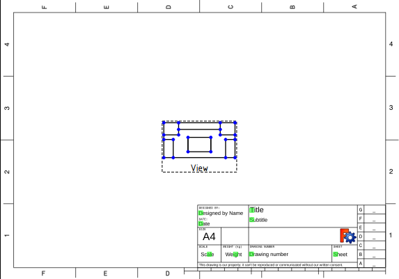
- Sélectionnez la Page dans la vue combinée et faites défiler jusqu'à la propriété Scale dans l'onglet Données.
- Modifiez l'échelle de 1 à 2 et appuyez sur Entrée. La vue grossira.
- Faites glisser la vue loin du cartouche en bas à droite de la page.
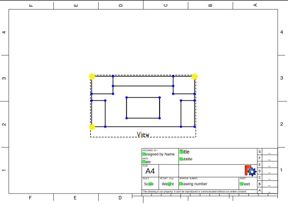
C'est mieux, mais un peu ennuyeux. Ajoutons quelques dimensions.
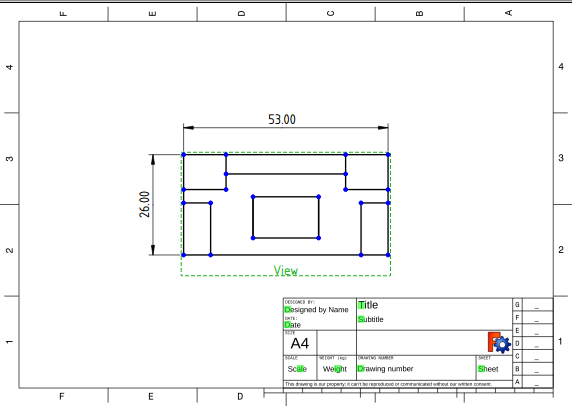
- Sélectionnez (bouton gauche de la souris) le sommet supérieur gauche (petit point), puis sélectionnez également (Ctrl+bouton gauche de la souris) sur le sommet inférieur gauche.
- Cliquez sur File:TechDraw Dimension Vertical.png Nouvelle cote verticale. Faites glisser le texte de cote hors du corps.
- Essayez à nouveau avec les sommets supérieur à gauche et supérieur droit et File:TechDraw Dimension Horizontal.png Nouvelle cote horizontale.
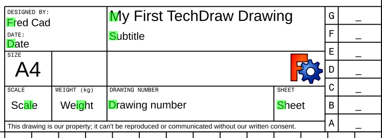
Editable Text
We should add some documentation to our drawing.
- Click on the small green square beside Title in the documentation block. You'll get a pop-up window where you can change Title to something more meaningful.
- Just for practice, put your name in the Designed by Name field the same way.
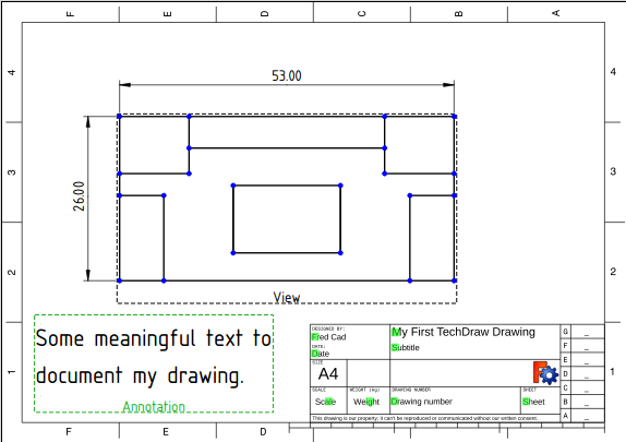
Getting better. Let's add some text to the page.
- Click on File:Techdraw-annotation.png New Annotation. A text block will appear in the middle of the page.
- Drag the text block away from the main View.
- Click on Annotation in the Combo view and scroll to the Text property on the Data tab.
- Click in the data area, the click on the ellipsis at the right of the field. You'll get a pop-up window where you can change the text to something more meaningful.
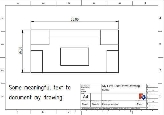
Before we leave this Page, let's see what it will look like when we print it.
- Click on File:TechDraw Toggle.png Toggle Frames. The Vertices and View frames will disappear. You can get them back by clicking Toggle again.
Multiple Views of a Single Part
Let's create a multiview drawing using a different Template as a starting point. We'll be using the First Angle convention, but you can change to Third Angle if that is your local convention.
- Click on File:TechDraw New Pick.png New Pick. A file chooser dialog will appear. Select a template file. We're going to use "ANSIB.SVG". A new tab will appear.
- Select "Body" and "Page001" (if you have more than one page in your document, you need to tell TechDraw which one to use).
- Click on File:Techdraw-projgroup.png New Projection Group. The familiar small view in the middle of the page will appear and a dialog will appear in the Task panel.
- Click on several boxes in the Secondary Views section of the dialog.
- Drag the View labelled "Front". All the other Views move with it.
- Change the Scale drop down box from Page to Custom and change the Custom Scale to 2:1. Press the OK button.
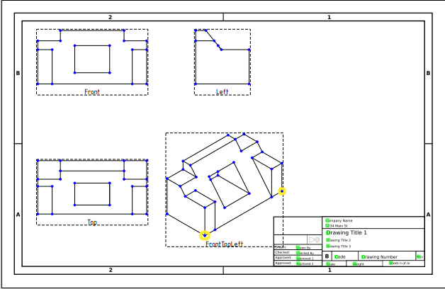
- In the View labelled "TopLeftFront", select the two Vertices at the extreme ends of the front edge of the work piece.
- Click on File:TechDraw Dimension Length.png New Length. Drag the dimension text away from the Body.
Linking Dimensions to 3D Model
Do you notice a problem with the dimension we just created?
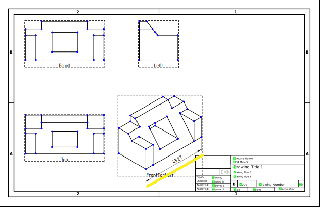
From the first part of this tutorial, we know that the work piece is 53 mm wide, but our new dimensions reads 43.27. This is because "TopLeftFront" is an isometric projection, and our first drawing was an orthogonal projection. To get the right value, we need to link our dimension directly to the 3D model.
- Note the name of our faulty dimension in the Combo panel. We'll need it in a minute.
- Change to the 3D tab and select the Vertices at the ends of the front edge of the work piece. Also select Page001.
- Click on File:TechDraw Dimension Link.png New Links. A dialog will open in the Task panel.
- In the dialog, move our dimension from the Available column to the Selected column. Press OK.
- Return to Page001. Our dimension should now read the correct value of 53. (if you still see 43.27, you may need to press the Recompute button or drag the dimension value a bit until it changes.)
Going Further
In this tutorial you have learning enough about TechDraw to produce a drawing like this one (by NormandC). See Note 2.

There is much more functionality in TechDraw for you to explore - Section Views, Detail Views, Svg Symbols, Images, face hatching.
Notes
- There is an excellent set of suggested preferences in this Forum post.
- This drawing was produced in v0.18. It shows dimensions in the proper format for an isometric view. In v0.17 the extension lines will be perpendicular to the edge rather than aligned with the axes.
Additional Resources
- TechDraw Wiki pages
- FreeCAD file of this exercise for comparison (made with 0.17) Download