Basic Part Design Tutorial/de: Difference between revisions
HarryGeier (talk | contribs) (Created page with "Ein Video der Schritte in diesem Teil des Tutorials ist hier: https://youtu.be/cUyPnCMeTgg") |
HarryGeier (talk | contribs) (Created page with "=== Formelement ""Tasche"" und externe Geometrie === Mit der Maus oder den Ansichtssymbolen drehen Sie das Modell um, so dass Sie seine Rückseite sehen können. Sobald die...") |
||
| Line 44: | Line 44: | ||
https://youtu.be/cUyPnCMeTgg |
https://youtu.be/cUyPnCMeTgg |
||
=== |
=== Formelement ""Tasche"" und externe Geometrie === |
||
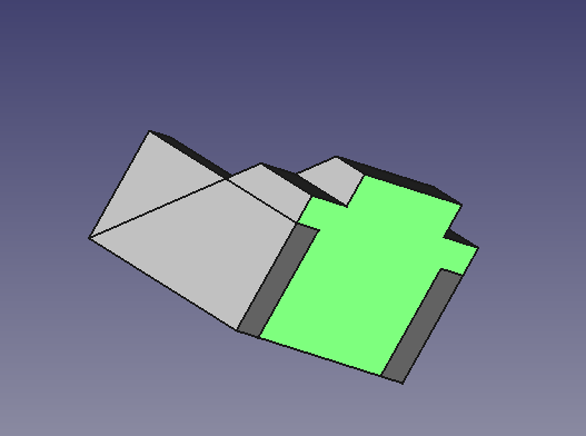
Mit der Maus oder den Ansichtssymbolen drehen Sie das Modell um, so dass Sie seine Rückseite sehen können. Sobald die Rückseite des Teils sichtbar ist, wählen Sie die Rückseite aus, indem Sie darauf klicken, wie im nächsten Bild zu sehen ist. |
|||
Using the mouse or the view icons turn the model around so you can see its back. Once the back of the part is visible, select the back face by clicking on it as seen in the next image. |
|||
[[Image:PD_WB_Tutorial003.png|center]] |
[[Image:PD_WB_Tutorial003.png|center]] |
||
After the face is selected, click on the New sketch icon in the toolbar or from the Part Design menu and that will map our next sketch to the back face of the part. Now select [[File:Sketcher_CreateRectangle.png|32px]] rectangle tool and place a rectangle on the rear face of the part in a similar fashion as shown below. Now following the steps listed, constrain the sketch. |
After the face is selected, click on the New sketch icon in the toolbar or from the Part Design menu and that will map our next sketch to the back face of the part. Now select [[File:Sketcher_CreateRectangle.png|32px]] rectangle tool and place a rectangle on the rear face of the part in a similar fashion as shown below. Now following the steps listed, constrain the sketch. |
||
Revision as of 12:16, 17 April 2018
| Topic |
|---|
| Modeling |
| Level |
| Beginner |
| Time to complete |
| Untere einer Stunde |
| Authors |
| HarryGeier (HarryGeier) |
| FreeCAD version |
| 0.17 or higher |
| Example files |
| Basic Part Design for v0.17 |
| See also |
| None |
Dieses Tutorial richtet sich an Anfänger und beschreibt einige, aber nicht alle, Werkzeuge und Techniken des Arbeitsbereichs Part Design. Dem Leser wird dabei Schritt für Schritt erklärt, wie das in der nachfolgenden Abbildung sichtbare Modell mittels Skizzen in FreeCAD erstellt werden kann.
Dieses Tutorial basiert auf Basic Part Design Tutorial von Quick61 mit Änderungen für die Version v0.17.
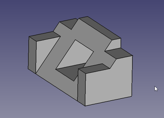
Ein Video (englisch) der kompletten Konstruktion finden Sie hier: https://youtu.be/geIrH1cOCzc
( Für jeden Teilbereich gibt es auch ein einzelnes Video )
Vorwort
Die Aufgabe
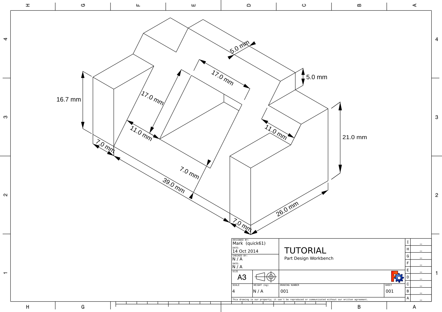
In diesem Tutorial verwenden Sie den Part Design Arbeitsbereich (Workbench), um ein 3D-Volumenmodell des in der Zeichnung (Drawing) gezeigten Teils zu erstellen. Alle notwendigen Abmessungen, um diese Aufgabe zu erfüllen, sind angegeben. Sie beginnen damit, dass Sie eine Kernform aus einer Basisskizze erstellen und dann auf dieser Form aufbauen, indem Sie sogenannte Features hinzufügen. Diese Features oder Formelemente fügen entweder dem Material Material hinzu oder entfernen es mithilfe zusätzlicher Skizzen und begleitender Feature-Operationen. Dieses Tutorial wird nicht alle Funktionen und Werkzeuge verwenden, die in der Part Design Workbench verfügbar sind, sollte aber das nötige verwenden, um dem Benutzer dieses Tutorials eine grundlegende Grundlage zu geben, auf der er sein Wissen und seine Fähigkeiten aufbauen kann.
Das Bauteil
Konstruieren des Teils
Start
Beginnen Sie zuerst damit, dass Sie in die Part Design Workbench wechseln. Dort sollten Sie ein neues Dokument erstellen, wenn Sie dies noch nicht getan haben.
Es empfiehlt sich, die Arbeit oft zu speichern, also speichern Sie das neue Dokument vor der Bearbeitung und geben Sie ihm einen beliebigen Namen.
Alle Arbeiten in Part Design beginnen mit einem Bauteil (Body). ![]() Klicken Sie auf diese Schaltfläche, um ein neues Bauteil zu erstellen und es zu aktivieren. Das Bauteil enthält am Ende mindestens einen Festkörper (Solid). Hier erstellen wir diesen aus einer Skizze (Sketcher)
Klicken Sie auf diese Schaltfläche, um ein neues Bauteil zu erstellen und es zu aktivieren. Das Bauteil enthält am Ende mindestens einen Festkörper (Solid). Hier erstellen wir diesen aus einer Skizze (Sketcher) ![]() . Klicken Sie auf diese Schaltfläche, um eine neue Skizze innerhalb des gerade erstellten Bauteils zu erstellen. Die erste Skizze basiert auf einer Ebene aus dem Ursprung (Origin). Wählen Sie hier die YZ_Ebene (Plane).
. Klicken Sie auf diese Schaltfläche, um eine neue Skizze innerhalb des gerade erstellten Bauteils zu erstellen. Die erste Skizze basiert auf einer Ebene aus dem Ursprung (Origin). Wählen Sie hier die YZ_Ebene (Plane).
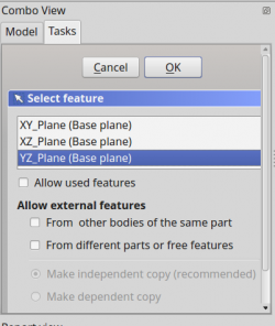
Nun erscheint im 3D Fenster der Skizziermodus(Sketch)
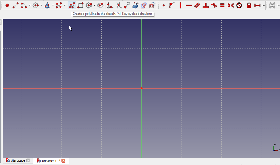
Als nächstes wollen Sie das Polylinien-Werkzeug ![]() verwenden und eine Form ähnlich der im nächsten Bild erstellen. Es muss nicht perfekt sein, da die endgültige Form mit Einschränkungen gemacht wird. Sobald Sie die Grundform haben, werden wir anfangen, die Einschränkungen anzuwenden. Wenn Sie die automatischen Beschränkungen aktiviert haben, werden einige dieser Einschränkungen automatisch angewendet. Wenn nicht, führen Sie die folgenden Schritte aus.
verwenden und eine Form ähnlich der im nächsten Bild erstellen. Es muss nicht perfekt sein, da die endgültige Form mit Einschränkungen gemacht wird. Sobald Sie die Grundform haben, werden wir anfangen, die Einschränkungen anzuwenden. Wenn Sie die automatischen Beschränkungen aktiviert haben, werden einige dieser Einschränkungen automatisch angewendet. Wenn nicht, führen Sie die folgenden Schritte aus.
- Wählen Sie die zwei horizontalen Linien mit der Maus aus, indem Sie darauf klicken, dann klicken Sie nach der Auswahl auf die horizontale Bedingung
 .
. - Wählen Sie die vertikale Linie auf der rechten Seite und klicken Sie dann auf die vertikale Einschränkung
 .
. - Wählen Sie die Anfangs- und Endpunkte Ihrer Polylinie und klicken Sie auf die Bedingung
 , um die Polylinie zu schließen.
 - Wählen Sie die untere horizontale Linie und die rechte vertikale Linie aus und wenden Sie an und
 Gleichheits-Beschränkung.
 - Wählen Sie entweder die horizontale oder die vertikale Linie und wenden Sie entweder eine entsprechende horizontale
 oder vertikale
  vertikale Distanz an und geben Sie einen Wert von 26 mm ein .
 - Wählen Sie die obere horizontale Linie aus und wenden Sie die horizontale Abstandsbeschränkung an und geben Sie einen Wert von 5 mm ein.
- Wählen Sie den unteren rechten Punkt(Endpunkt) der horizontalen Linie und dann den Mittelpunkt des Rasters und wenden Sie die 32px Koinzidenz-Beschränkung, um Ihre Form zu fixieren.
An diesem Punkt sollten Sie eine vollständig eingeschränkte Skizze haben, wie durch die Farbe und die in der Combo-Ansicht angezeigte Nachricht angezeigt. Es sollte jetzt genau wie das Bild unten aussehen.
Klicken Sie nun in der Combo-Ansicht auf die Schaltfläche Schließen, um den Skizzenbearbeitungsmodus zu verlassen, und wählen Sie ![]() Pad aus der Symbolleiste oder aus dem Teilentwurfsmenü. Dies gibt Ihnen ein Pad-Dialogfeld in der Combo-Ansicht. Wählen Sie in diesem Dialogfeld zuerst das Pulldown-Menü Typ aus und dann Zwei Dimensionen. Die Zeichnung am Anfang dieses Tutorials sagt, dass das Teil 53 mm lang ist. Wir tun dies, indem wir unsere Skizze in beide Richtungen von der Mittelebene aus auffüllen, um diese Distanz zu bilden, d. H., Machen das Kissen symmetrisch bezüglich der Skizzierebene. Der Grund dafür wird später beim Erstellen von Features angezeigt. Für jetzt, da wir wollen, dass es insgesamt 53 mm lang ist, werden wir 26,5 für die Länge und 26,5 für die zweite Länge eingeben. Alternativ können Sie eine einzelne Länge von 53 mm bereitstellen und auf das Kontrollkästchen Symmetrisch zu Ebene klicken. Sobald das erledigt ist, haben wir nun unsere Basis, auf der wir zusätzliche Features hinzufügen werden, um unser Teil zu konstruieren.
Pad aus der Symbolleiste oder aus dem Teilentwurfsmenü. Dies gibt Ihnen ein Pad-Dialogfeld in der Combo-Ansicht. Wählen Sie in diesem Dialogfeld zuerst das Pulldown-Menü Typ aus und dann Zwei Dimensionen. Die Zeichnung am Anfang dieses Tutorials sagt, dass das Teil 53 mm lang ist. Wir tun dies, indem wir unsere Skizze in beide Richtungen von der Mittelebene aus auffüllen, um diese Distanz zu bilden, d. H., Machen das Kissen symmetrisch bezüglich der Skizzierebene. Der Grund dafür wird später beim Erstellen von Features angezeigt. Für jetzt, da wir wollen, dass es insgesamt 53 mm lang ist, werden wir 26,5 für die Länge und 26,5 für die zweite Länge eingeben. Alternativ können Sie eine einzelne Länge von 53 mm bereitstellen und auf das Kontrollkästchen Symmetrisch zu Ebene klicken. Sobald das erledigt ist, haben wir nun unsere Basis, auf der wir zusätzliche Features hinzufügen werden, um unser Teil zu konstruieren.
Ein Video der Schritte in diesem Teil des Tutorials ist hier: https://youtu.be/cUyPnCMeTgg
Formelement ""Tasche"" und externe Geometrie
Mit der Maus oder den Ansichtssymbolen drehen Sie das Modell um, so dass Sie seine Rückseite sehen können. Sobald die Rückseite des Teils sichtbar ist, wählen Sie die Rückseite aus, indem Sie darauf klicken, wie im nächsten Bild zu sehen ist.
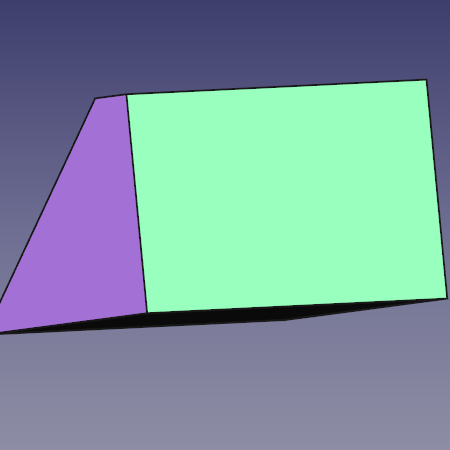
After the face is selected, click on the New sketch icon in the toolbar or from the Part Design menu and that will map our next sketch to the back face of the part. Now select ![]() rectangle tool and place a rectangle on the rear face of the part in a similar fashion as shown below. Now following the steps listed, constrain the sketch.
rectangle tool and place a rectangle on the rear face of the part in a similar fashion as shown below. Now following the steps listed, constrain the sketch.
- Select one of the horizontal lines apply a horizontal distance constraint and a value of 5 mm.
- Select one of the vertical lines and give it a vertical distance constraint and a value of 11 mm.
- Use
 External geometry tool and select the upper right vertex of the face and click it so you are provided a point from the external geometry to link our sketch to.
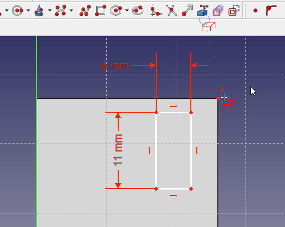
Select that point you just made available with the External geometry tool and then select the upper right vertex of the rectangle and click on the coincident constraint. At this point the sketch should be fully constrained and look like the next image.
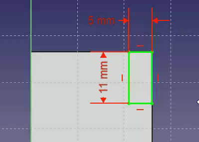
Once that is done, click the Close button at the top of the Tasks tab in the Combo View window, then select ![]() Pocket tool from the toolbar or Part Design menu. Using this tool is the opposite of the Pad tool. As the Pad tool adds material to the part, the Pocket tool removes material from the part. Both operations are called features. In this Pocket operation we want to select Through all from the type pulldown-menu and then click the OK button.
Pocket tool from the toolbar or Part Design menu. Using this tool is the opposite of the Pad tool. As the Pad tool adds material to the part, the Pocket tool removes material from the part. Both operations are called features. In this Pocket operation we want to select Through all from the type pulldown-menu and then click the OK button.
For the next operation, make sure that “Pocket” is selected in the Model tree view and once done, click on ![]() the Mirror feature on the toolbar or from the Part Design menu. In the Mirror dialog in the Combo View, select Horizontal sketch axis from the Plane pulldown menu. Then click OK. The Mirror feature works in this way because the base feature of our model was Padded both ways from the horizontal plane in the first operation with the base sketch. If all has gone well, you should now have a part that looks like the image below after you orbit it around to the front.
the Mirror feature on the toolbar or from the Part Design menu. In the Mirror dialog in the Combo View, select Horizontal sketch axis from the Plane pulldown menu. Then click OK. The Mirror feature works in this way because the base feature of our model was Padded both ways from the horizontal plane in the first operation with the base sketch. If all has gone well, you should now have a part that looks like the image below after you orbit it around to the front.
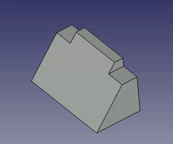
A video of the steps used in this portion of the tutorial is here: https://youtu.be/wiGXV9G7mrM
Features with pad and external geometry
After taking a look, orbit back around and once again select the back face of the part and select that face to map the next sketch to.
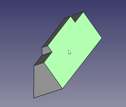
Select New sketch and make a new rectangle in the manner similar to what is shown below in the next image. Then proceed to add dimensional constraints to the rectangle.
- Select a horizontal line and apply a horizontal distance constraint with a value of 16.7.
- Select a vertical line and apply a vertical distance constraint of 7 mm
- Using the External geometry tool, select the upper left vertex of the part face.
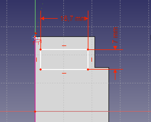
Now selecting the upper left vertex of the rectangle and the external geometry point, click on the coincident constraint to fully constrain the sketch.
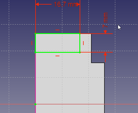
Next we will click on the Pad feature and in the Pad dialog in the Combo View we want a length of 26 mm leaving the type as Dimension and then placing a check on the Reversed checkbox. Using the Reversed checkbox will cause the Pad to go into the part instead of away from the part. This operation provides with the following result.

Once again use the Mirror feature to get the second pad. First ensure that created Pad is selected in the tree view, then click on Mirror in the toolbar of select it from the Part Design menu. We will repeat the operation we did for Pocket above and select Horizontal sketch axis from the Plane pulldown menu.
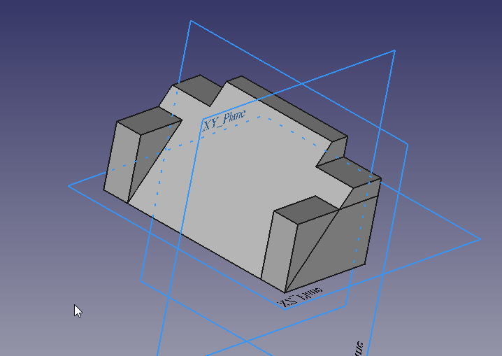
A video of the steps used in this portion of the tutorial is here: https://youtu.be/Ido1owp8ubc
Feature with pocket and external geometry
At this point orbiting the part around to the front, we can see that our part is now starting to look like the part in the dimensioned drawing at the beginning of this tutorial. Once you have the view of the front, click on the sloped face with your mouse to select the face we will use for the next sketch.
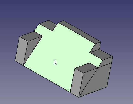
Here we will use the rectangle tool and place a rectangle in our sketch and once having done so, apply the following constraints.
- Select a horizontal line and a vertical line, and after both are selected, click on the Equals constraint.
- Select either a horizontal or vertical line and apply a corresponding horizontal or vertical distance constraint with a value of 17 mm
- Using the External geometry tool, select the top right vertex as shown in the image below.
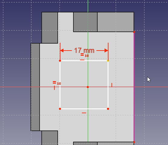
Now using the dimensions from the drawing, apply the following constraints.
- Select the external geometry point and the upper right vertex of the now square sketch and apply a horizontal distance constraint of 7 mm
- Select the external geometry point and the upper right vertex of the now square sketch and apply a vertical distance constraint of 11 mm
The result should be as follows.
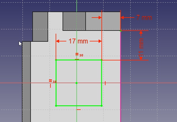
At this point if we were to simply Pocket this sketch, the resulting hole would be perpendicular to the sloped face that it is mapped to, and this is not what we want.
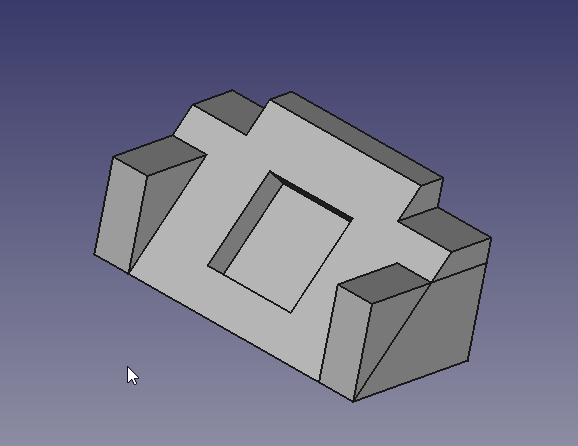
We want the hole to be perpendicular to the back face, but it's projected dimensions are not the 17 mm x 17 mm dimensions that are given in the drawing. Now we could do the math and calculate the dimensions needed, or we can use the tools provided in FreeCAD to make that projection for us.
A video of the steps used in this portion of the tutorial is here: https://youtu.be/x4d5nZPWCLQ
To create pocket which has the sloped rectangle as it´s outlet, we draw a new rectangle on the rear side, using the projection of the sloped rectangle as an external reference.
Orbit the Solid around to see the rear face of the part once again and select the back face to map the final sketch to.
Select New Sketch ![]() from the toolbar or Part Design menu. Now in sketch edit mode, we do not see the sketched rectangle of the slope. To make it selectable , we switch the combo view to model tab and select the last sketch made (Sketch003) on the sloped plane. Then using the spacebar, make it visible. Next, select the mirror feature above (mirrored001) and again using spacebar, hide it. Then you should see the rectangle inside the 3D View. You may continue to work with the model tab visible, or switch back to tasks tab. Using the
from the toolbar or Part Design menu. Now in sketch edit mode, we do not see the sketched rectangle of the slope. To make it selectable , we switch the combo view to model tab and select the last sketch made (Sketch003) on the sloped plane. Then using the spacebar, make it visible. Next, select the mirror feature above (mirrored001) and again using spacebar, hide it. Then you should see the rectangle inside the 3D View. You may continue to work with the model tab visible, or switch back to tasks tab. Using the ![]() External geometry tool, select the upper and lower horizontal edges of the sloped rectangle.
External geometry tool, select the upper and lower horizontal edges of the sloped rectangle.
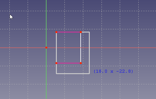
- Select the upper left vertex of the rectangle and the upper left point of the external geometry and click on the coincident constraint.
- Click on the lower right vertex of the rectangle and the lower right point of the external geometry and click on the coincident constraint.
And we should end up with this.
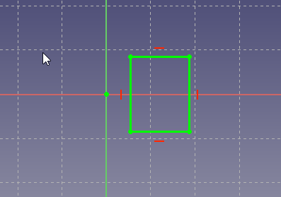
For the final step in this tutorial, close the sketcher window using close or fish editing from the context menu of sketch004 and then select the ![]() Pocket feature from the toolbar or from the Part Design menu. From the Type pulldown select Through all and click the OK button.
Pocket feature from the toolbar or from the Part Design menu. From the Type pulldown select Through all and click the OK button.
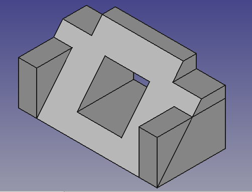
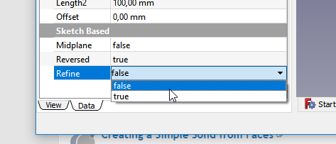
At this point, you will see some lines which come from intersecting features. In this case the side block intersects with the base profile letting it appear as a triangular block above the profile. To remove these lines, you can either switch on "refine shape" in your Part Design Settings or , to save some processing speed and still have these lines while constructing, individually switch it on at each feature, which will create such lines. The Setting on feature level can be done in the "data" tab of the feature. Set the refine property to TRUE to invoke refining.

A video of these steps of the tutorial is here: https://youtu.be/UYI0gvxCYeI
This tutorial and your model are complete.
Additional Resources
- Links to accompanying video have been included.
- FreeCAD file for comparison (made with 0.17) Download
