Transient FEM analysis
Background
Creating the model
Starting with a blank FreeCAD project, we build our bimetal strip in the Part workbench: First, we draw a ![]() Cube Solid and rename it to 'aluminium'. We give it the dimensions 100 x 10 x 2 mm (length x width x height). We create a second Cube Solid 'steel' with the same dimensions and offset it 2 mm along the z-axis (via Placement > Position > z). We select both solids (using the Shift key and your mouse) and create
Cube Solid and rename it to 'aluminium'. We give it the dimensions 100 x 10 x 2 mm (length x width x height). We create a second Cube Solid 'steel' with the same dimensions and offset it 2 mm along the z-axis (via Placement > Position > z). We select both solids (using the Shift key and your mouse) and create ![]() Boolean Fragments from them, which we rename to 'bimetal strip'. In the data panel, we change the mode from 'Standard' to 'CompSolid'. (It should also work by using the
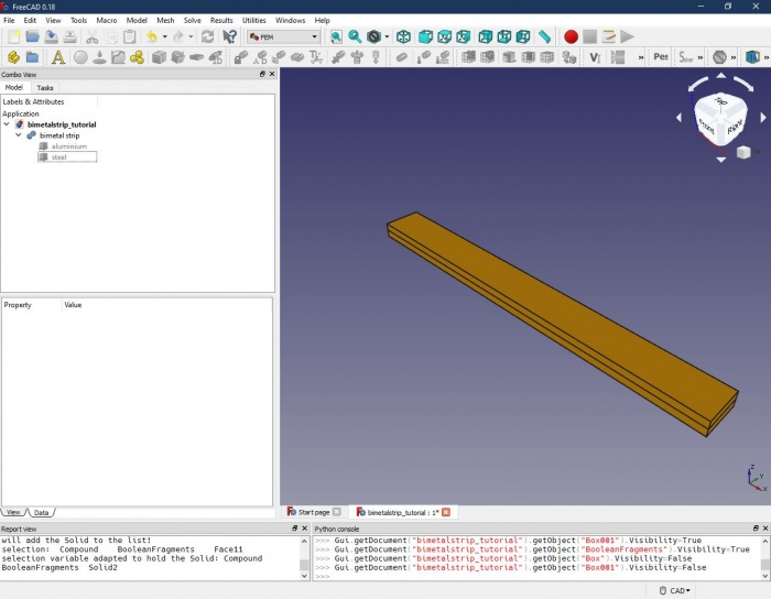
Boolean Fragments from them, which we rename to 'bimetal strip'. In the data panel, we change the mode from 'Standard' to 'CompSolid'. (It should also work by using the ![]() Union command instead of Boolean Fragments, however, with more complex intersecting shapes, there might be trouble with the FEM analysis later. So, better get used to using Boolean Fragments in the first place.) The result should look like this:
Union command instead of Boolean Fragments, however, with more complex intersecting shapes, there might be trouble with the FEM analysis later. So, better get used to using Boolean Fragments in the first place.) The result should look like this:
Preparing and running the FEM analysis
Assigning the materials
In the FEM workbench we create a new analysis and add a new
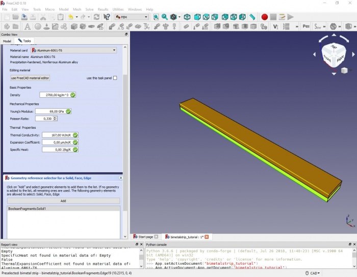
material to the analysis. In the upcoming task window, we select one of the predefined aluminium alloys. Under 'geometry reference selector', we assign the material to the lower strip of our model by setting the selection mode to 'solid', clicking 'add' and selecting a face or an edge of the lower strip. In the list view, 'BooleanFragments:Solid1' should show up.
We close the task window and repeat the steps to create a second material 'Steel' (material card 'CalculiX-Steel') and assign it to the top strip ('BooleanFragments:Solid2').
Creating the mesh
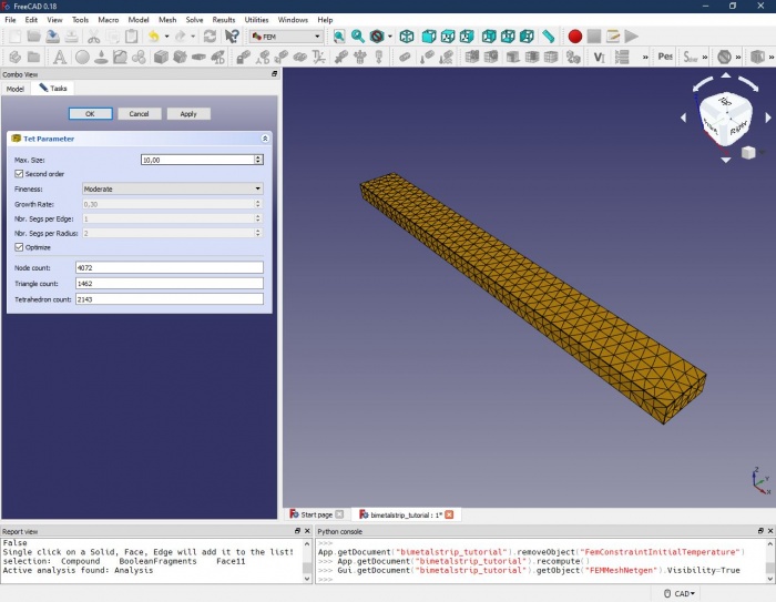
Since a Finite Element Analysis obviously needs elements to work with, we have to dissect our model into a so-called mesh. The FEM workbench offers two meshing tools: Netgen and GMSH. We will go with Netgen here: With the Boolean Fragments objects 'bimetal strip' selected, we click on the Netgen icon in the FEM workbench. In the upcoming task window, we have to make different selections, starting from the top:
- Max. size is the maximum size (in millimetres) of an element. The smaller the maximum element size, the more elements we get – usually the result will get more precise, but with a dramatic increase in computing time. We set it to 10.
- Second order means, that in each element, additional nodes will be created. This increases computing time, but is usually a good choice if it comes to bending as in our analysis. We leave it checked.
- Fineness: Select, how finely the model should be cut into elements. For more complex models with curvatures and intersections, we can increase the element number in those regions to get better results (at the cost of more computing time, of course). Expert users can also set it to User-defined and set the following parameters. For our simple rectangular model, the fineness selection has not much of an impact, we keep it at moderate level.
- Optimize: Some kind of post-processing after meshing. We keep it checked.
A click on 'Apply' runs the mesher, and – the time depending on your computer – a wireframe appears on our model. The mesher should have created about 4,000 nodes.


