Transient FEM analysis: Difference between revisions
Luftschraube (talk | contribs) |
Luftschraube (talk | contribs) |
||
| Line 10: | Line 10: | ||
Go to the FEM workbench and create a new [[File:Fem-analysis.svg|20px]] analysis. Add a new [[File:Fem-material.svg|20px]] material to the analysis. In the upcoming task window, select one of the predefined aluminium alloys. Under "geometry reference selector", we now have to assign the material to the lower strip of our model: Set the selection mode to 'solid', click 'add' and select a face or an edge of the lower strip. In the list view, 'BooleanFragments:Solid1' should show up. |
Go to the FEM workbench and create a new [[File:Fem-analysis.svg|20px]] analysis. Add a new [[File:Fem-material.svg|20px]] material to the analysis. In the upcoming task window, select one of the predefined aluminium alloys. Under "geometry reference selector", we now have to assign the material to the lower strip of our model: Set the selection mode to 'solid', click 'add' and select a face or an edge of the lower strip. In the list view, 'BooleanFragments:Solid1' should show up. |
||
[[File: |
[[File:Transient FEM Bimetal (2).JPG|700px]] |
||
Close the material editor task window. Repeat the steps to create a second material 'Steel' (material card 'CalculiX-Steel') and assign it to the top strip ('BooleanFragments:Solid2'). |
Close the material editor task window. Repeat the steps to create a second material 'Steel' (material card 'CalculiX-Steel') and assign it to the top strip ('BooleanFragments:Solid2'). |
||
Revision as of 07:25, 30 August 2019
Background
Creating the model
Starting with a blank FreeCAD project, we build our bimetal strip in the Part workbench: First, draw a ![]() Cube Solid and rename it to “aluminium”. Give it the dimensions 100 x 10 x 2 mm (length x width x height). Create a second Cube Solid “steel” with the same dimensions and offset it 2 mm along the z-axis (via Placement > Position > z). Select both solids (using the Shift key and your mouse) and create
Cube Solid and rename it to “aluminium”. Give it the dimensions 100 x 10 x 2 mm (length x width x height). Create a second Cube Solid “steel” with the same dimensions and offset it 2 mm along the z-axis (via Placement > Position > z). Select both solids (using the Shift key and your mouse) and create ![]() Boolean Fragments from them. Rename the Boolean Fragments object to “bimetal strip” and in the data panel, change the mode from “Standard” to “CompSolid”. (It should also work by using the
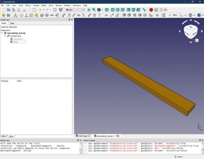
Boolean Fragments from them. Rename the Boolean Fragments object to “bimetal strip” and in the data panel, change the mode from “Standard” to “CompSolid”. (It should also work by using the ![]() Union command instead of Boolean Fragments, however, with more complex intersecting shapes, there might be trouble with the FEM analysis later. So, better get used to using Boolean Fragments in the first place.) The result should look like this:
Union command instead of Boolean Fragments, however, with more complex intersecting shapes, there might be trouble with the FEM analysis later. So, better get used to using Boolean Fragments in the first place.) The result should look like this:
Preparing and running the FEM analysis
Assigning the materials
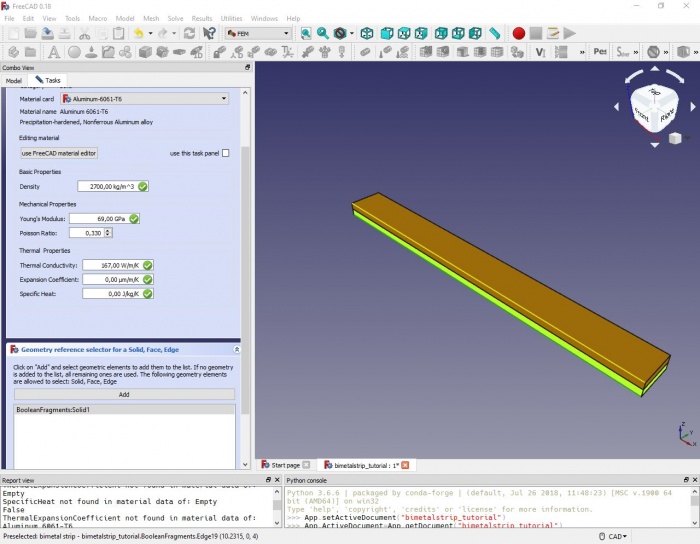
Go to the FEM workbench and create a new analysis. Add a new
material to the analysis. In the upcoming task window, select one of the predefined aluminium alloys. Under "geometry reference selector", we now have to assign the material to the lower strip of our model: Set the selection mode to 'solid', click 'add' and select a face or an edge of the lower strip. In the list view, 'BooleanFragments:Solid1' should show up.
Close the material editor task window. Repeat the steps to create a second material 'Steel' (material card 'CalculiX-Steel') and assign it to the top strip ('BooleanFragments:Solid2').

