Toothbrush Head Stand/fr: Difference between revisions
m (petite correction) |
(Updating to match new version of source page) |
||
| Line 1: | Line 1: | ||
{{TutorialInfo |
{{TutorialInfo|Topic=Modeling|Level=Beginner|Author=[[User:EmmanuelG|EmmanuelG]]|Time=1 hour|FCVersion=0.16 or greater|Files=[https://www.thingiverse.com/thing:2403310 Thingiverse 2403310]}} |
||
== |
== A daily-life problem == |
||
Les brosses à dent électriques sont rarement accompagnées d'un support pour les brossettes, alors que dans une famille vous verrez souvent plusieurs brossettes être utilisées avec un seul corps. |
|||
Si l'on observe une plateforme comme Thingiverse, on y trouvera 200-800 projets sur ce thème ! Signe que de nombreuses personnes partagent effectivement le même problème commun. |
|||
Voici le type d'objet typiquement imaginé et comment le modéliser. |
|||
Electric toothbrushes rarely come with a head stand, while in a family you will often see multiple heads used with one body. Many people facing a common problem lead us to a variety of solutions, as you can see on Thingiverse (200-800 projects are related to that). Here is the first answer and how to design it. |
|||
Ce tutoriel vous guidera à travers les étapes requises pour modéliser la pièce suivante à l'aides des outils de bases de l'[[PartDesign Workbench/fr|Atelier Part Design]] (la totalité des outils et possibilités ne seront pas couverts). |
|||
This tutorial will take you through the steps needed to model the part shown in the image below using basic tools from the [[PartDesign Workbench|Part Design Workbench]] (many of the tools and capabilities are not covered). |
|||
[[Image:TBHS-model.png|center]] |
[[Image:TBHS-model.png|center]] |
||
== |
== First idea : a plate == |
||
* |
*From the start-page, select [[Image:Workbench_PartDesign.png]] ''Part Design'', or create a new document and select the ''Part Design'' workbench. |
||
[[Image:TBHS-0.png|center]] |
[[Image:TBHS-0.png|center]] |
||
=== |
=== Create a sketch === |
||
* |
*Click on [[Image:Sketcher_NewSketch.png|32px]] [[Sketcher_NewSketch|'''New sketch''']]. Either from the contextual task menu at the left, or the toolbar above or from the Part Design menu at the top. |
||
[[File:TBHS-1.JPG|800px|center]] |
[[File:TBHS-1.JPG|800px|center]] |
||
A dialog prompts you to choose the sketch orientation and provide an offset. |
|||
Une boite de dialogue s'ouvre et vous demande de choisir l'orientation de l'esquisse ainsi qu'un décalage éventuel. |
|||
* |
*We will pick the XY Plane as shown in the image above (that orientation correspond to the common build plate of most 3D printers), then click OK. |
||
[[File:TBHS-2.JPG|800px|center]] |
[[File:TBHS-2.JPG|800px|center]] |
||
You now are facing the XY plane from above, and have access to the drawing tools. |
|||
Vous faites maintenant face au plan XY, et avez accès aux outils de dessins. |
|||
* |
* Click on [[File:Sketcher_CreateRectangle.png|32px]] [[Sketcher_Rectangle|'''Rectangle''']]. |
||
* |
* Click to place a first point. |
||
* Click to place the opposite corner. |
|||
* Cliquez pour positionner le coin opposé. |
|||
* |
* Press {{KEY|ESC}} or click the right mouse button to stop using the tool. |
||
[[File:TBHS-3.JPG|800px|center]] |
[[File:TBHS-3.JPG|800px|center]] |
||
You now have a floating rectangle of unspecified dimensions. |
|||
* Click on a line of the rectangle, you now have access to the constraint tools at the right of the toolbar (depending of the size of your screen you may need to drag them to the left in order to see them all) |
|||
* Cliquez sur un segment du rectangle, vous avez maintenant accès aux outils de contrainte à la droite de la barre d'outils (selon la taille de votre écran vous aurez peut-être besoin de faire glisser ce bloc de la barre d'outils sur la gauche pour tous les voirs) |
|||
* |
* Click on [[File:Constraint_Length.png|32px]] [[Constraint_Length|'''Length''']] |
||
* |
* A dialog prompts you to set a dimension. Enter 80mm, click OK. |
||
* |
* Repeat with the other side of the rectangle, also 80mm. |
||
[[File:TBHS-4.JPG|800px|center]] |
[[File:TBHS-4.JPG|800px|center]] |
||
You now have a floating square. |
|||
Vous avez maintenant un carré libre et sans dimensions. |
|||
* Click on the lower left point of the square. |
|||
* Cliquez sur le point en-bas à gauche du carré. |
|||
* Click on the origin of the XY plane (at the intersection of the two thick lines). |
|||
* Cliquez sur le point à l'origine du plan XY (au croisement des deux lignes principales). |
|||
* |
* Click on [[File:Constraint_PointOnPoint.png|32px]] [[Constraint_PointOnPoint|'''Coincident''']]. |
||
[[File:TBHS-5.JPG|800px|center]] |
[[File:TBHS-5.JPG|800px|center]] |
||
You now have a totally constrained sketch, as you are told by the solver on the left and the change of color. |
|||
Vous avez maintenant une esquisse totalement contrainte, comme dit par le solveur sur la gauche et le changement de couleur. |
|||
It is a good practice to always have a totally constrained sketch. |
|||
Il est recommandé de toujours avoir des esquisses totalement contraintes. |
|||
An under-constrained sketch can leave room for unwanted change, if you modify something later on. |
|||
Une esquisse sous-contrainte risque de laisser se produire des changements non-désirés, si vous modifiez un détail par la suite. |
|||
On the opposite, an over-constrained sketch is also not good. In that case the solver warn you of redundant constraints and you should remove some of them. |
|||
L'inverse n'est également pas souhaitable : une esquisse sur-contrainte. Dans ce cas le solveur vous averti également des contraintes redondantes, vous devrez supprimer celles qui sont en trop. |
|||
* |
* To leave the sketch, click either on the "Close" button on the left, or the [[File:Sketcher_LeaveSketch.png|32px]] icon in the toolbar, or press {{KEY|ESC}}. |
||
[[File:TBHS-6.JPG|800px|center]] |
[[File:TBHS-6.JPG|800px|center]] |
||
You now only see the square, and the contextual task menu on the left show you more options than before. |
|||
=== |
=== Create a pad === |
||
* |
* Click on [[Image:View-axometric.png|32px]] '''Axonometric''' among the standard views, to better see what will happen. |
||
* |
* Click on [[File:PartDesign_Pad.png|32px]] '''Pad'''. |
||
* |
* Enter 4mm and click OK. |
||
[[File:TBHS-7.JPG|800px|center]] |
[[File:TBHS-7.JPG|800px|center]] |
||
Your sketch is now in volume ! |
|||
=== |
=== Create a sketch on it === |
||
* Select the upper face |
|||
* Sélectionnez la face supérieure. |
|||
[[File:TBHS-8.JPG|800px|center]] |
[[File:TBHS-8.JPG|800px|center]] |
||
The color of the face change and you have more options in the contextual task menu. |
|||
* |
* Click on [[Image:Sketcher_NewSketch.png|32px]] '''New sketch'''. As a face was selected it will not ask you to choose a plane. |
||
[[File:TBHS-9.JPG|800px|center]] |
[[File:TBHS-9.JPG|800px|center]] |
||
* |
* Click on [[File:Sketcher_Circle.png|32px]] [[Sketcher_Circle|'''Circle''']], click to place the center, move the pointer and click to define the radius. |
||
* Draw 4 circles on the pad (of any size) |
|||
* Dessinez 4 cercles sur la surface (peu importe leur position ou leur taille). |
|||
* |
* Press {{KEY|ESC}} or click the right mouse button to stop using the tool. |
||
[[File:TBHS-10.JPG|800px|center]] |
[[File:TBHS-10.JPG|800px|center]] |
||
* Select the circles |
|||
* Sélectionnez les 4 cercles. |
|||
* |
* Click on [[File:Constraint_EqualLength.png|32px]] [[Constraint_EqualLength|'''Equal Length''']] |
||
[[File:TBHS-11.JPG|800px|center]] |
[[File:TBHS-11.JPG|800px|center]] |
||
Now the circles share the same radius. |
|||
Maintenant les cercles partagent le même rayon. |
|||
* |
* Click on [[File:Sketcher_External.png|32px]] [[Sketcher_External|'''External geometry''']]. |
||
* |
* Click on the four sides of the square, it add lines, color magenta. |
||
[[File:TBHS-12.JPG|800px|center]] |
[[File:TBHS-12.JPG|800px|center]] |
||
Theses lines will serve as reference to position the circles. |
|||
Ces lignes vont servir de référence pour positionner les cercles. |
|||
* |
* Use [[File:Constraint_Length.png|32px]] [[Constraint_Length|'''Length''']] to position them at 20mm from the edges. |
||
[[File:TBHS-13.JPG|800px|center]] |
[[File:TBHS-13.JPG|800px|center]] |
||
* |
* Click on a circle |
||
* |
* Click on [[File:Constraint_Radius.png|32px]] [[Constraint_Radius|'''Radius''']] and set it at 1,5mm. |
||
[[File:TBHS-14.JPG|800px|center]] |
[[File:TBHS-14.JPG|800px|center]] |
||
* |
* To leave the sketch, click either on the "Close" button on the left, or the [[File:Sketcher_LeaveSketch.png|32px]] icon in the toolbar, or press {{KEY|ESC}}. |
||
[[File:TBHS-15.JPG|800px|center]] |
[[File:TBHS-15.JPG|800px|center]] |
||
=== |
=== Create a pad=== |
||
* |
* Click on [[Image:View-axometric.png|32px]] '''Axonometric''' among the standard views, to better see what will happen. |
||
* |
* Click on [[File:PartDesign_Pad.png|32px]] '''Pad'''. |
||
* |
* Enter 25mm and click OK. |
||
[[File:TBHS-16.JPG|800px|center]] |
[[File:TBHS-16.JPG|800px|center]] |
||
You have the basic shape, it just need final touches. |
|||
=== |
=== Rounding the corners === |
||
* |
* Holding {{KEY|CTRL}} click on the vertical edge at each corner to select the four of them. |
||
Don't hesitate to help you by switching the display mode (just at the left of the Axonometric View) between [[File:DrawStyleWireFrame.svg|32px]] '''Wireframe''' and [[File:DrawStyleFlatLines.svg|32px]] '''Wireframe and shadow'''. |
|||
[[File:TBHS-17.JPG|800px|center]] |
[[File:TBHS-17.JPG|800px|center]] |
||
* |
* Click on [[File:PartDesign_Fillet.png|32px]] [[PartDesign_Fillet|'''Fillet''']]. |
||
* |
* Set the radius at 20mm. |
||
[[File:TBHS-18.JPG|800px|center]] |
[[File:TBHS-18.JPG|800px|center]] |
||
Much better. |
|||
C'est tout de suite mieux. |
|||
=== |
=== Making it more robust === |
||
We need to add material at the base of the cylinders to make them less prone to snap. Because of the printing orientation these small surfaces will be fragile at the junction with the base. |
|||
Nous allons ajouter de la matière à la base des cylindres, pour les renforcer. Car le sens d'impression et leur petite surface en font des zones fragile, à la jonction avec la plaque. |
|||
* |
* Select the circles at the base of the cylinders |
||
[[File:TBHS-19.JPG|800px|center]] |
[[File:TBHS-19.JPG|800px|center]] |
||
* |
* Click on [[File:PartDesign_Chamfer.png|32px]] [[PartDesign_Chamfer|'''Chamfer''']]. |
||
* Set it to 2mm. |
|||
* Spécifiez 2mm et cliquez sur OK. |
|||
[[File:TBHS-20.JPG|800px|center]] |
[[File:TBHS-20.JPG|800px|center]] |
||
=== |
=== Chamfer the edges === |
||
* |
* Select the face under the base, add a [[File:PartDesign_Chamfer.png|32px]] '''Chamfer''' of 0,5mm. |
||
The first layer of plastic is often being squashed a little too much, this will compensate that and save you time in cleaning the model. If the first layer is ok that will make it only nicer |
|||
La première couche d'une pièce imprimée est parfois un peu trop écrasée, ceci permettra de compenser cet effet sur les bords de la pièce, et donc du temps de nettoyage/limage pour nettoyer le modèle. Si la première couche est bien le modèle n'en sera que plus joli. |
|||
[[File:TBHS-21.JPG|800px|center]] |
[[File:TBHS-21.JPG|800px|center]] |
||
* |
* Select the edges at the border of the upper face (holding {{KEY|CTRL}} ). |
||
[[File:TBHS-23.JPG|800px|center]] |
[[File:TBHS-23.JPG|800px|center]] |
||
* |
* Add a [[File:PartDesign_Chamfer.png|32px]] '''Chamfer''' of 1mm. This one is only aesthetic. |
||
[[File:TBHS-22.JPG|800px|center]] |
[[File:TBHS-22.JPG|800px|center]] |
||
| Line 188: | Line 187: | ||
Tadaa ! |
Tadaa ! |
||
== Export |
== Export as a .STL == |
||
* In the Combo View on the left, select the tree view instead of the contextual task menu, click on the last feature (the chamfer). |
|||
* Dans la vue combinée sur la gauche, sélectionnez l'onglet "Modèle" (au lieu de l'onglet "Tâche"), cliquez sur la dernière opération (Chamfer). |
|||
[[File:TBHS-24.JPG|800px|center]] |
[[File:TBHS-24.JPG|800px|center]] |
||
* |
* Now you can select "Export..." from the File menu at the top left, and select the file format .STL. |
||
* Just print it :-) |
|||
* Il ne vous reste plus qu'à le fabriquer :-) |
|||
== Inspiration == |
== Inspiration == |
||
The above model make a good starting point to use FreeCAD, but as a toothbrush head stand it have its flaws : due to the print orientation and small surface the sticks are prone to break. |
|||
Ce premier modèle constitue un bon démarrage pour utiliser FreeCAD, mais comme porte-brossettes il a ses défauts : les picos risquent de casser à cause de leur petite surface et du sens d'impression. |
|||
Inspired by the variety of solutions other people came up with, we will make this second version which will be much better. |
|||
Inspirés par la variétés des solutions imaginées par d'autres personnes, nous allons créer ce second modèle qui sera bien plus résistant tout en étant plus esthétique. |
|||
[[File:TBHS-v2.jpg|800px|center]] |
[[File:TBHS-v2.jpg|800px|center]] |
||
Don't worry it is often needed to go through several revision for an idea (e.g. : once the prototype on the picture was used, we added more space between the heads so that they should not touch). |
|||
Ne vous inquietez pas, il est souvent nécessaire pour une idée de faire l'objet de plusieurs versions avant d'atteindre un stade suffisamment abouti (par ex. après utilisation du prototype ci-dessus nous avons augmenté l'espace entre les têtes afin d'éviter qu'elles ne se touchent). |
|||
In this second part you will also learn to use more tools, like the powerful ''Linear repetition''. |
|||
Dans cette seconde partie vous allez également apprendre à utiliser d'autres outils, dont le puissant "Répétition linéaire". |
|||
== |
== Second idea : a band == |
||
* |
*Create a new document and select the [[Image:Workbench_PartDesign.png]] ''Part Design'' workbench. |
||
=== |
=== Create a sketch === |
||
* |
*Create a [[Image:Sketcher_NewSketch.png|32px]] '''New sketch''', on the XY plan. |
||
[[File:TBHS-1.JPG|800px|center]] |
[[File:TBHS-1.JPG|800px|center]] |
||
* |
*Draw a [[Image:Sketcher_CreateSlot.png|32px]] [[Sketcher_Slot|'''Slot''']] |
||
**Click to place the first center |
|||
**Cliquez pour placer le premier centre |
|||
**Move to define the length and radius |
|||
**Déplacez le curseur pour définir la longueur et le rayon |
|||
** |
**Click to set the second center. |
||
[[File:TBHS2-1.JPG|800px|center]] |
[[File:TBHS2-1.JPG|800px|center]] |
||
You now have a floating slot of unspecified dimensions. |
|||
Vous avez à présent une rainure flottante et non-dimensionnée. |
|||
* Click on one of the horizontal line of the slot |
|||
* Cliquez sur un des segments horizontaux de la rainure |
|||
* |
* Click on [[File:Constraint_Length.png|32px]] [[Constraint_Length|'''Length''']] |
||
* |
* A dialog prompts you to set a dimension. Enter 75mm, click OK. |
||
** that's for a 3 head stand, count 25mm for each, if you want more |
|||
** ceci correspond à un support pour 3 brossettes, comptez 25m par tête, si vous vouliez en faire un plus grand. |
|||
[[File:TBHS2-2.JPG|800px|center]] |
[[File:TBHS2-2.JPG|800px|center]] |
||
* Click on one point of the horizontal line |
|||
* Cliquez sur un point à l'extrémité d'un segment horizontal |
|||
* |
* Click on one point of the other horizontal line |
||
* |
* Click on [[File:Constraint_Length.png|32px]] [[Constraint_Length|'''Length''']] |
||
* |
* A dialog prompts you to set a dimension. Enter 29mm, click OK. |
||
[[File:TBHS2-3.JPG|800px|center]] |
[[File:TBHS2-3.JPG|800px|center]] |
||
* |
*Draw a [[Image:Sketcher_CreateSlot.png|32px]] [[Sketcher_Slot|'''Slot''']] around the first slot. |
||
[[File:TBHS2-4.JPG|800px|center]] |
[[File:TBHS2-4.JPG|800px|center]] |
||
* |
*Make the centers of the second slot coincident with the centers of the first slot with [[File:Constraint_PointOnPoint.png|32px]] [[Constraint_PointOnPoint|'''Coincident''']]. |
||
[[File:TBHS2-5.JPG|800px|center]] |
[[File:TBHS2-5.JPG|800px|center]] |
||
* |
* Click on one point of the horizontal line of the first slot |
||
* |
* Click on one point of the nearest horizontal line of the second slot |
||
* |
* Click on [[File:Constraint_Length.png|32px]] [[Constraint_Length|'''Length''']] |
||
* |
* A dialog prompts you to set a dimension. Enter 3mm, click OK. |
||
[[File:TBHS2-6.JPG|800px|center]] |
[[File:TBHS2-6.JPG|800px|center]] |
||
*To make the sketch fully constrained |
|||
*Pour rendre l'esquisse totalement contrainte |
|||
**Click on the lower left point of the second slot |
|||
**Cliquez sur le point en bas à gauche de la rainure extérieure |
|||
** |
**Click on the origin of the XY plan |
||
** |
**Click on [[File:Constraint_PointOnPoint.png|32px]] [[Constraint_PointOnPoint|'''Coincident''']] |
||
[[File:TBHS2-7.JPG|800px|center]] |
[[File:TBHS2-7.JPG|800px|center]] |
||
* |
* To leave the sketch, click either on the "Close" button on the left, or the [[File:Sketcher_LeaveSketch.png|32px]] icon in the toolbar, or press {{KEY|ESC}}. |
||
[[File:TBHS2-8.JPG|800px|center]] |
[[File:TBHS2-8.JPG|800px|center]] |
||
=== |
=== Create a pad === |
||
* |
* Click on [[Image:View-axometric.png|32px]] '''Axonometric''' among the standard views, to better see what will happen. |
||
* |
* Click on [[File:PartDesign_Pad.png|32px]] '''Pad'''. |
||
* |
* Enter 30mm and click OK. |
||
[[File:TBHS2-9.JPG|800px|center]] |
[[File:TBHS2-9.JPG|800px|center]] |
||
=== Créer une esquisse dessus === |
|||
=== Create a sketch on it === |
|||
* Sélectionnez la face extérieure suivante. |
|||
*Select the upper face |
|||
[[File:TBHS2-10.JPG|800px|center]] |
[[File:TBHS2-10.JPG|800px|center]] |
||
* |
*Create a [[Image:Sketcher_NewSketch.png|32px]] '''New sketch'''. As a face was selected it will not ask you to choose a plane. |
||
[[File:TBHS2-11.JPG|800px|center]] |
[[File:TBHS2-11.JPG|800px|center]] |
||
* |
*Draw an [[Image:Sketcher_CreateHexagon.png|32px]] [[Sketcher_Hexagon|'''Hexagon''']] |
||
**Click to place the center |
|||
**Cliquez pour placer le centre |
|||
**Move to define the radius |
|||
**Déplacez le curseur pour définir le rayon |
|||
**Click to set |
|||
**Cliquez pour le définir |
|||
[[File:TBHS2-12.JPG|800px|center]] |
[[File:TBHS2-12.JPG|800px|center]] |
||
*Click on an edge of the hexagon |
|||
*Cliquez sur un coté de l'hexagone |
|||
* |
*Click on [[Image:Constraint_Horizontal.png|32px]] [[Constraint_Horizontal|'''Horizontal''']] |
||
[[File:TBHS2-13.JPG|800px|center]] |
[[File:TBHS2-13.JPG|800px|center]] |
||
* Click on the center of the hexagon |
|||
* Cliquez sur le centre de l'hexagone |
|||
* Click on the horizontal line of the XY plane |
|||
* Cliquez sur la ligne horizontale du plan XY (les abscisses). |
|||
* |
* Click on [[File:Constraint_Length.png|32px]] [[Constraint_Length|'''Length''']] |
||
* |
* A dialog prompts you to set a dimension. Enter 15mm, click OK. |
||
[[File:TBHS2-14.JPG|800px|center]] |
[[File:TBHS2-14.JPG|800px|center]] |
||
* Click on the center of the hexagon |
|||
* Cliquez sur le centre de l'hexagone |
|||
* Click on the vertical of the XY plane |
|||
* Cliquez sur la ligne verticale du plan XY (les ordonnées) |
|||
* |
* Click on [[File:Constraint_Length.png|32px]] [[Constraint_Length|'''Length''']] |
||
* |
* A dialog prompts you to set a dimension. Enter 10mm, click OK. |
||
[[File:TBHS2-15.JPG|800px|center]] |
[[File:TBHS2-15.JPG|800px|center]] |
||
* Click on the blue circle of the hexagon |
|||
* Cliquez sur le cercle bleu de l'hexagone |
|||
* |
* Click on [[File:Constraint_Radius.png|32px]] [[Constraint_Radius|'''Radius''']] |
||
* |
* A dialog prompts you to set a dimension. Enter 8mm, click OK. |
||
[[File:TBHS2-16.JPG|800px|center]] |
[[File:TBHS2-16.JPG|800px|center]] |
||
* |
* To leave the sketch, click either on the "Close" button on the left, or the [[File:Sketcher_LeaveSketch.png|32px]] icon in the toolbar, or press {{KEY|ESC}}. |
||
[[File:TBHS2-17.JPG|800px|center]] |
[[File:TBHS2-17.JPG|800px|center]] |
||
=== |
=== Create a hole === |
||
* |
* Click on [[Image:View-axometric.png|32px]] '''Axonometric''' among the standard views, to better see what will happen. |
||
* |
* Click on [[File:PartDesign_Pocket.png|32px]] [[PartDesign_Pocket|'''Pocket''']]. |
||
* |
* Select ''to the first'' in the dropdown menu and click OK. |
||
[[File:TBHS2-18.JPG|800px|center]] |
[[File:TBHS2-18.JPG|800px|center]] |
||
=== Répétition linéaire === |
|||
=== Linear repetition === |
|||
* Dans la vue combinée sur la gauche, sélectionnez l'onglet "Modèle", cliquez sur le dernier élément "Pocket" |
|||
* In the Combo View on the left, select the tree view instead of the contextual task menu, click on the pocket feature. |
|||
* Cliquez sur [[File:PartDesign_LinearPattern.png|32px]] [[PartDesign_LinearPattern/fr|'''Répétition linéaire''']] |
|||
* Click on [[File:PartDesign_LinearPattern.png|32px]] [[PartDesign_LinearPattern|'''LinearPattern''']]. |
|||
* Spécifiez la longueur à 55mm et le nombre d’occurrences à 3, cliquez sur OK |
|||
* Set the length at 55mm and occurencies at 3, then click OK. |
|||
[[File:TBHS2-19.JPG|800px|center]] |
[[File:TBHS2-19.JPG|800px|center]] |
||
=== |
=== Create a sketch on it === |
||
*Select the inner face |
|||
*Sélectionner la face intérieure suivante. |
|||
[[File:TBHS2-20.JPG|800px|center]] |
[[File:TBHS2-20.JPG|800px|center]] |
||
* |
*Create a [[Image:Sketcher_NewSketch.png|32px]] '''New sketch'''. As a face was selected it will not ask you to choose a plane. |
||
[[File:TBHS2-21.JPG|800px|center]] |
[[File:TBHS2-21.JPG|800px|center]] |
||
* |
* Click on [[File:Sketcher_Circle.png|32px]] [[Sketcher_Circle|'''Circle''']], click to place the center, move the pointer and click to define the radius. |
||
[[File:TBHS2-22.JPG|800px|center]] |
[[File:TBHS2-22.JPG|800px|center]] |
||
* Click on the center of the circle |
|||
* Cliquez sur le centre du cercle |
|||
* Click on the horizontal line of the XY plane |
|||
* Cliquez sur la ligne horizontale du plan XY (les abscisses). |
|||
* |
* Click on [[File:Constraint_Length.png|32px]] [[Constraint_Length|'''Length''']] |
||
* |
* A dialog prompts you to set a dimension. Enter 15mm, click OK. |
||
[[File:TBHS2-23.JPG|800px|center]] |
[[File:TBHS2-23.JPG|800px|center]] |
||
* Click on the center of the circle |
|||
* Cliquez sur le centre du cercle |
|||
* Click on the vertical of the XY plane |
|||
* Cliquez sur la ligne verticale du plan XY (les ordonnées) |
|||
* |
* Click on [[File:Constraint_Length.png|32px]] [[Constraint_Length|'''Length''']] |
||
* |
* A dialog prompts you to set a dimension. Enter 10mm, click OK. |
||
[[File:TBHS2-24.JPG|800px|center]] |
[[File:TBHS2-24.JPG|800px|center]] |
||
* |
* Click on the circle |
||
* |
* Click on [[File:Constraint_Radius.png|32px]] [[Constraint_Radius|'''Radius''']] |
||
* |
* A dialog prompts you to set a dimension. Enter 3.5mm, click OK. |
||
[[File:TBHS2-25.JPG|800px|center]] |
[[File:TBHS2-25.JPG|800px|center]] |
||
* |
* To leave the sketch, click either on the "Close" button on the left, or the [[File:Sketcher_LeaveSketch.png|32px]] icon in the toolbar, or press {{KEY|ESC}}. |
||
[[File:TBHS2-26.JPG|800px|center]] |
[[File:TBHS2-26.JPG|800px|center]] |
||
=== Créer un volume === |
|||
=== Create a pad === |
|||
* Cliquez sur [[Image:View-axometric.png|32px]] '''Axonométrique''' parmi les vues standards, pour mieux voir ce qu'il va se passer. |
|||
* |
* Click on [[Image:View-axometric.png|32px]] '''Axonometric''' among the standard views, to better see what will happen. |
||
* Click on [[File:PartDesign_Pad.png|32px]] '''Pad'''. |
|||
* Spécifiez 4mm et cliquez sur OK. |
|||
* Enter 4mm and click OK. |
|||
[[File:TBHS2-27.JPG|800px|center]] |
[[File:TBHS2-27.JPG|800px|center]] |
||
=== |
=== Linear repetition === |
||
* In the Combo View on the left, select the tree view instead of the contextual task menu, click on the pad feature. |
|||
* Dans la vue combinée sur la gauche, sélectionnez l'onglet "Modèle", cliquez sur le dernier élément "Pad" |
|||
* |
* Click on [[File:PartDesign_LinearPattern.png|32px]] [[PartDesign_LinearPattern|'''LinearPattern''']]. |
||
* |
* Set the length at 55mm and occurencies at 3, then click OK. |
||
[[File:TBHS2-28.JPG|800px|center]] |
[[File:TBHS2-28.JPG|800px|center]] |
||
=== Dépouille === |
|||
=== Draft === |
|||
*Sélectionnez le coté de chaque cylindres |
|||
*Select the side of each round pads |
|||
[[File:TBHS2-29.JPG|800px|center]] |
[[File:TBHS2-29.JPG|800px|center]] |
||
* |
* Click on [[File:PartDesign_Draft.png|32px]] [[PartDesign_Draft|'''Draft''']]. |
||
* |
* Set the draft angle at 40°. |
||
* |
* Click on "Neutral plane" and select the face on which the sketch is drawn. |
||
* |
* Tick "Invert the draft direction". |
||
[[File:TBHS2-30.JPG|800px|center]] |
[[File:TBHS2-30.JPG|800px|center]] |
||
We could have used a chamfer to do something similar, but the draft is more appropriate in this case. |
|||
Nous pourrions avoir utilisé la fonction "Chanfrein" pour faire quelque chose de similaire, mais la fonction "Dépouille" est plus appropriée ici. |
|||
Chamfer = left / Draft = right |
|||
[[File:TBHS2-30-chamfer.JPG|200px]][[File:TBHS2-30-draft.JPG|200px]] |
[[File:TBHS2-30-chamfer.JPG|200px]][[File:TBHS2-30-draft.JPG|200px]] |
||
=== Finitions === |
=== Finitions === |
||
* |
*Holding {{KEY|CTRL}} select the bottom and top faces. |
||
[[File:TBHS2-31-bottom.JPG|200px]][[File:TBHS2-31-top.JPG|200px]] |
[[File:TBHS2-31-bottom.JPG|200px]][[File:TBHS2-31-top.JPG|200px]] |
||
* |
** Add a [[File:PartDesign_Chamfer.png|32px]] '''Chamfer''' of 0,5mm. |
||
[[File:TBHS2-31.JPG|800px|center]] |
[[File:TBHS2-31.JPG|800px|center]] |
||
Perfect ! |
|||
== Export |
== Export as a .STL == |
||
* In the Combo View on the left, select the tree view instead of the contextual task menu, click on the last feature (the chamfer). |
|||
* Dans la vue combinée sur la gauche, sélectionnez l'onglet "Modèle" (au lieu de l'onglet "Tâche"), cliquez sur la dernière opération (Chamfer). |
|||
[[File:TBHS2-32.JPG|800px|center]] |
[[File:TBHS2-32.JPG|800px|center]] |
||
* |
* Now you can select "Export..." from the File menu at the top left, and select the file format .STL. |
||
* Print it instead of the first version or to replace it if it eventually broke ;-) |
|||
* Fabriquez celui-ci au lieu de la première version, ou pour la remplacer si elle a éventuellement été cassée ;-) |
|||
{{clear}} |
{{clear}} |
||
Revision as of 15:26, 25 March 2018
| Topic |
|---|
| Modeling |
| Level |
| Beginner |
| Time to complete |
| 1 hour |
| Authors |
| EmmanuelG |
| FreeCAD version |
| 0.16 or greater |
| Example files |
| Thingiverse 2403310 |
| See also |
| None |
A daily-life problem
Electric toothbrushes rarely come with a head stand, while in a family you will often see multiple heads used with one body. Many people facing a common problem lead us to a variety of solutions, as you can see on Thingiverse (200-800 projects are related to that). Here is the first answer and how to design it.
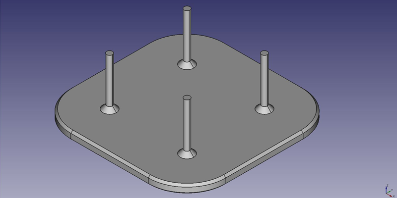
This tutorial will take you through the steps needed to model the part shown in the image below using basic tools from the Part Design Workbench (many of the tools and capabilities are not covered).
First idea : a plate
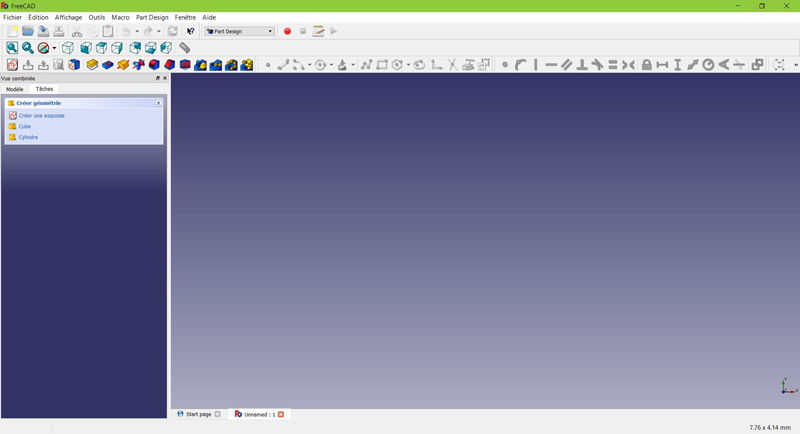
- From the start-page, select
 Part Design, or create a new document and select the Part Design workbench.
Create a sketch
- Click on
 New sketch. Either from the contextual task menu at the left, or the toolbar above or from the Part Design menu at the top.
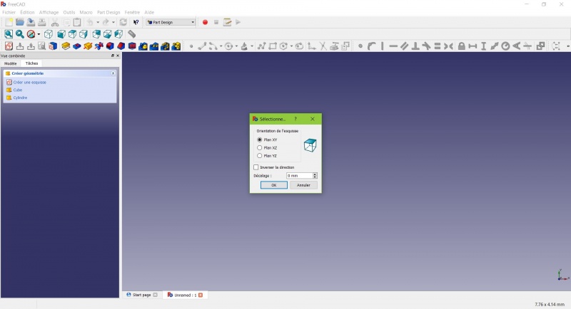
A dialog prompts you to choose the sketch orientation and provide an offset.
- We will pick the XY Plane as shown in the image above (that orientation correspond to the common build plate of most 3D printers), then click OK.
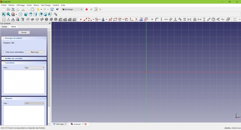
You now are facing the XY plane from above, and have access to the drawing tools.
- Click on
 Rectangle.
 - Click to place a first point.
- Click to place the opposite corner.
- Press ESC or click the right mouse button to stop using the tool.
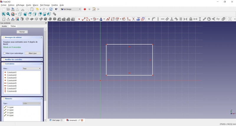
You now have a floating rectangle of unspecified dimensions.
- Click on a line of the rectangle, you now have access to the constraint tools at the right of the toolbar (depending of the size of your screen you may need to drag them to the left in order to see them all)
- Click on
 Length
 - A dialog prompts you to set a dimension. Enter 80mm, click OK.
- Repeat with the other side of the rectangle, also 80mm.
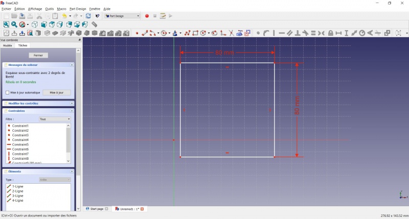
You now have a floating square.
- Click on the lower left point of the square.
- Click on the origin of the XY plane (at the intersection of the two thick lines).
- Click on
 Coincident.
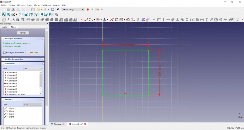
You now have a totally constrained sketch, as you are told by the solver on the left and the change of color.
It is a good practice to always have a totally constrained sketch.
An under-constrained sketch can leave room for unwanted change, if you modify something later on. On the opposite, an over-constrained sketch is also not good. In that case the solver warn you of redundant constraints and you should remove some of them.
- To leave the sketch, click either on the "Close" button on the left, or the
 icon in the toolbar, or press ESC.
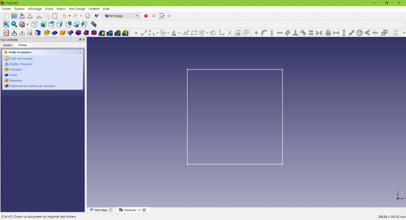
You now only see the square, and the contextual task menu on the left show you more options than before.
Create a pad
- Click on
 Axonometric among the standard views, to better see what will happen.
 - Click on
 Pad.
Pad. - Enter 4mm and click OK.
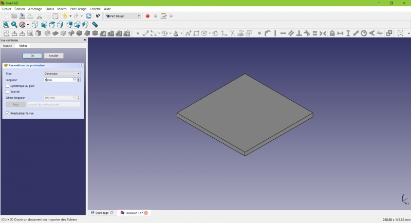
Your sketch is now in volume !
Create a sketch on it
- Select the upper face
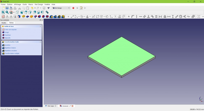
The color of the face change and you have more options in the contextual task menu.
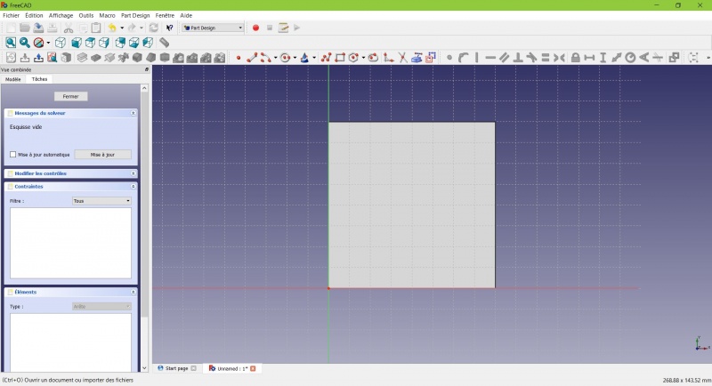
- Click on
 Circle, click to place the center, move the pointer and click to define the radius.
 - Draw 4 circles on the pad (of any size)
- Press ESC or click the right mouse button to stop using the tool.
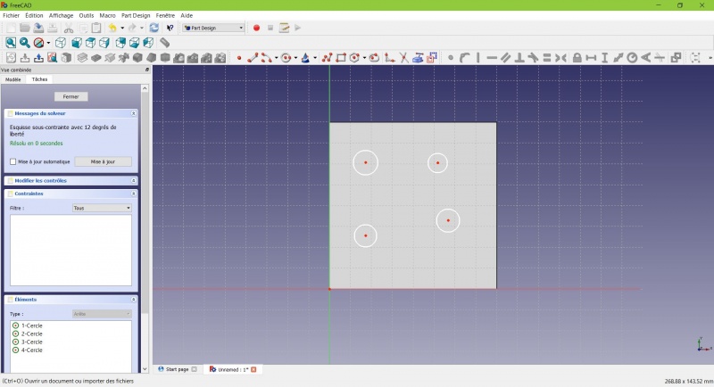
- Select the circles
- Click on
 Equal Length
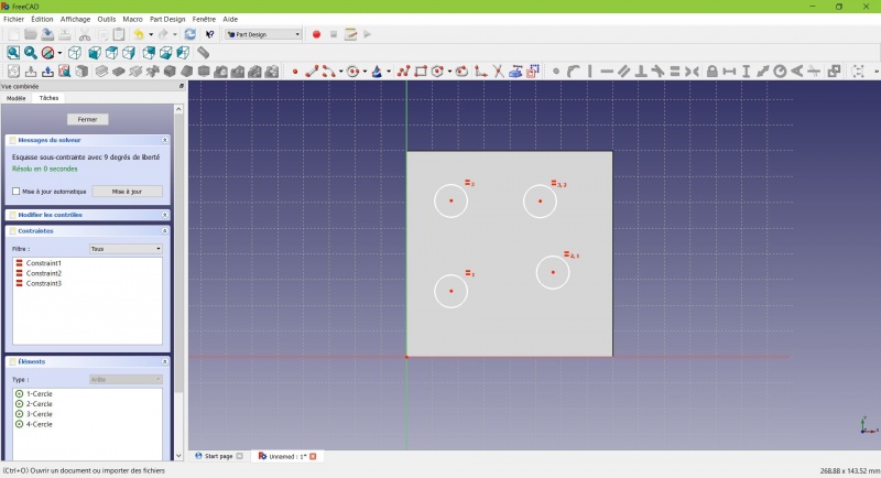
Now the circles share the same radius.
- Click on
 External geometry.
 - Click on the four sides of the square, it add lines, color magenta.
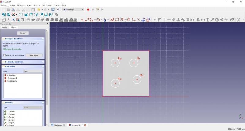
Theses lines will serve as reference to position the circles.
- Use
 Length to position them at 20mm from the edges.
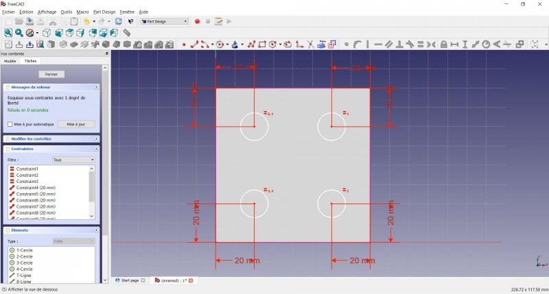
- Click on a circle
- Click on
 Radius and set it at 1,5mm.
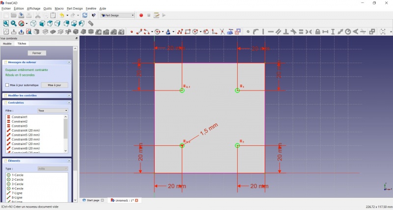
- To leave the sketch, click either on the "Close" button on the left, or the
 icon in the toolbar, or press ESC.
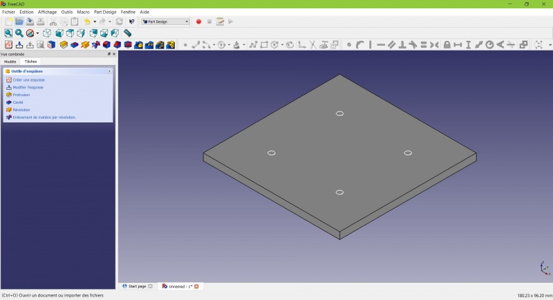
Create a pad
- Click on
 Axonometric among the standard views, to better see what will happen.
 - Click on
 Pad.
Pad. - Enter 25mm and click OK.
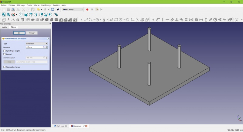
You have the basic shape, it just need final touches.
Rounding the corners
- Holding CTRL click on the vertical edge at each corner to select the four of them.
Don't hesitate to help you by switching the display mode (just at the left of the Axonometric View) between Wireframe and
Wireframe and shadow.
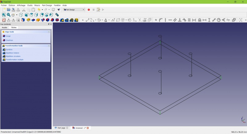
- Click on
 Fillet.
 - Set the radius at 20mm.
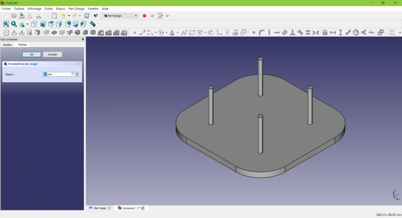
Much better.
Making it more robust
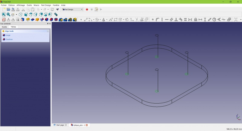
We need to add material at the base of the cylinders to make them less prone to snap. Because of the printing orientation these small surfaces will be fragile at the junction with the base.
- Select the circles at the base of the cylinders
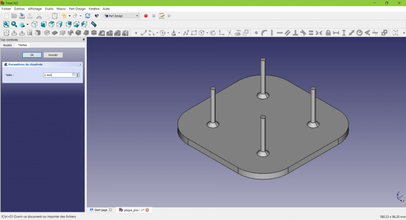
- Click on
 Chamfer.
 - Set it to 2mm.
Chamfer the edges
The first layer of plastic is often being squashed a little too much, this will compensate that and save you time in cleaning the model. If the first layer is ok that will make it only nicer
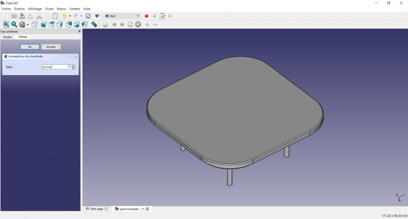
- Select the edges at the border of the upper face (holding CTRL ).
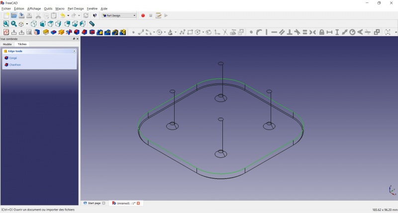
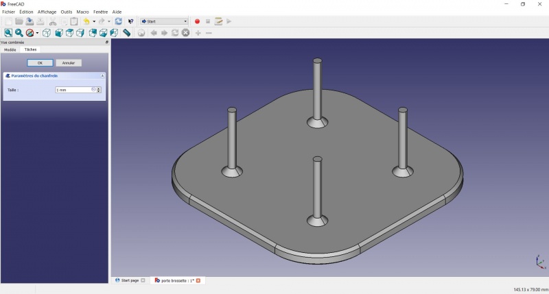
Tadaa !
Export as a .STL
- In the Combo View on the left, select the tree view instead of the contextual task menu, click on the last feature (the chamfer).
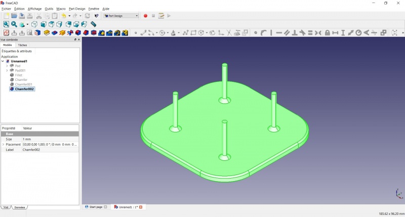
- Now you can select "Export..." from the File menu at the top left, and select the file format .STL.
- Just print it :-)
Inspiration
The above model make a good starting point to use FreeCAD, but as a toothbrush head stand it have its flaws : due to the print orientation and small surface the sticks are prone to break.
Inspired by the variety of solutions other people came up with, we will make this second version which will be much better.
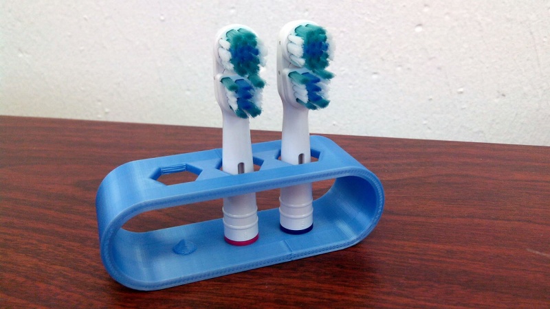
Don't worry it is often needed to go through several revision for an idea (e.g. : once the prototype on the picture was used, we added more space between the heads so that they should not touch).
In this second part you will also learn to use more tools, like the powerful Linear repetition.
Second idea : a band
Create a sketch

- Draw a
 Slot
Slot
- Click to place the first center
- Move to define the length and radius
- Click to set the second center.
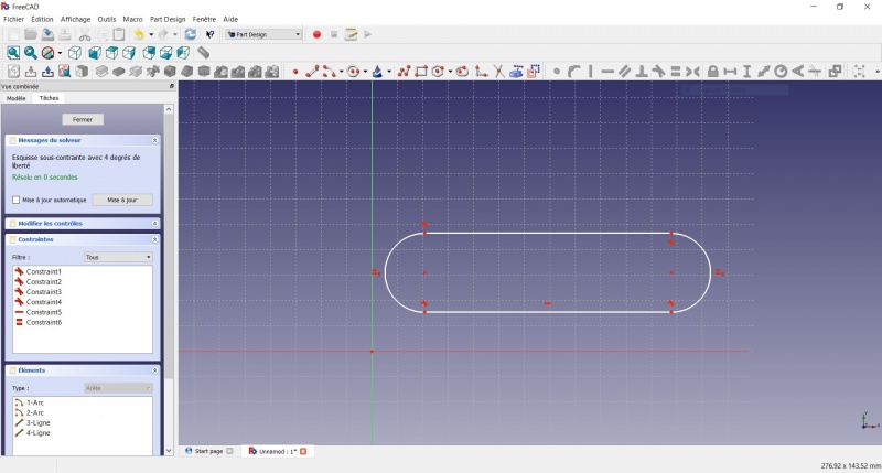
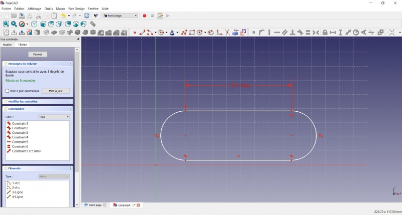
You now have a floating slot of unspecified dimensions.
- Click on one of the horizontal line of the slot
- Click on
 Length
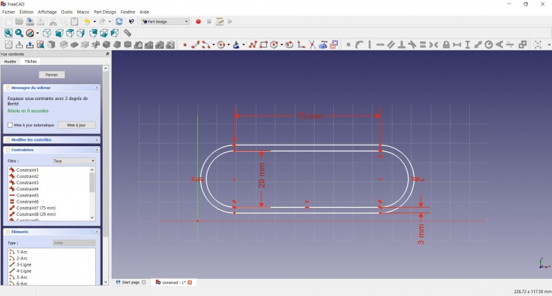
 - A dialog prompts you to set a dimension. Enter 75mm, click OK.
- that's for a 3 head stand, count 25mm for each, if you want more
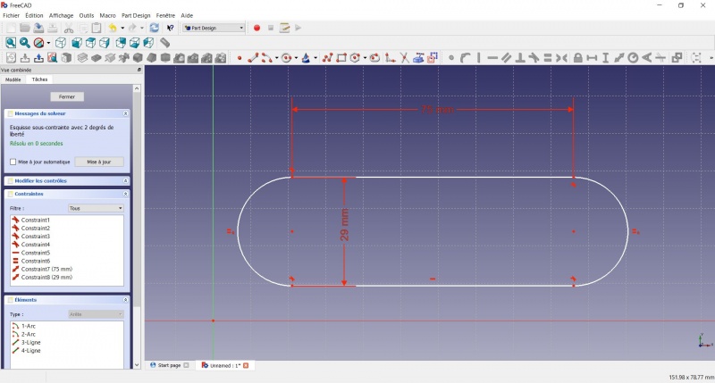
- Click on one point of the horizontal line
- Click on one point of the other horizontal line
- Click on
 Length
 - A dialog prompts you to set a dimension. Enter 29mm, click OK.
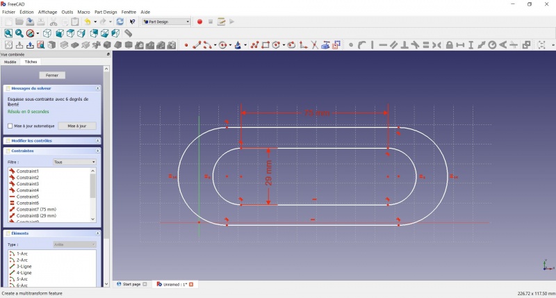
- Draw a
 Slot around the first slot.
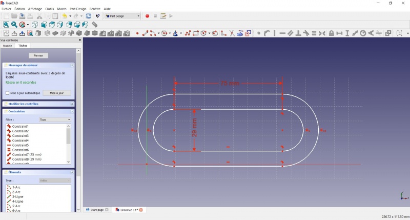
- Make the centers of the second slot coincident with the centers of the first slot with
 Coincident.
- Click on one point of the horizontal line of the first slot
- Click on one point of the nearest horizontal line of the second slot
- Click on
 Length
 - A dialog prompts you to set a dimension. Enter 3mm, click OK.
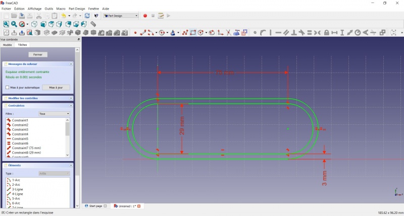
- To make the sketch fully constrained
- Click on the lower left point of the second slot
- Click on the origin of the XY plan
- Click on
 Coincident
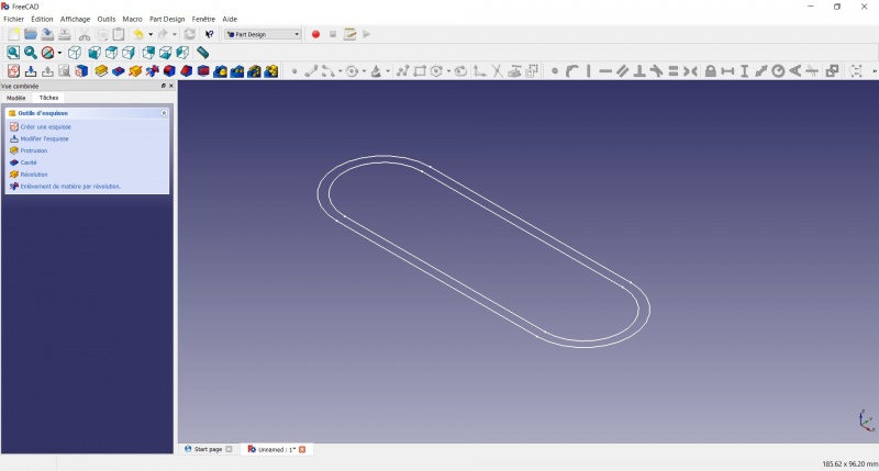
- To leave the sketch, click either on the "Close" button on the left, or the
 icon in the toolbar, or press ESC.
Create a pad
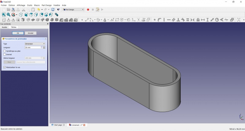
- Click on
 Axonometric among the standard views, to better see what will happen.
 - Click on
 Pad.
Pad. - Enter 30mm and click OK.
Create a sketch on it
- Select the upper face
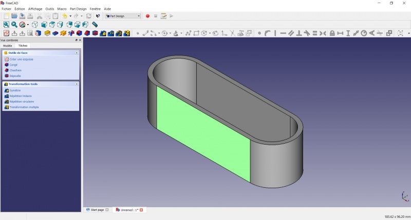
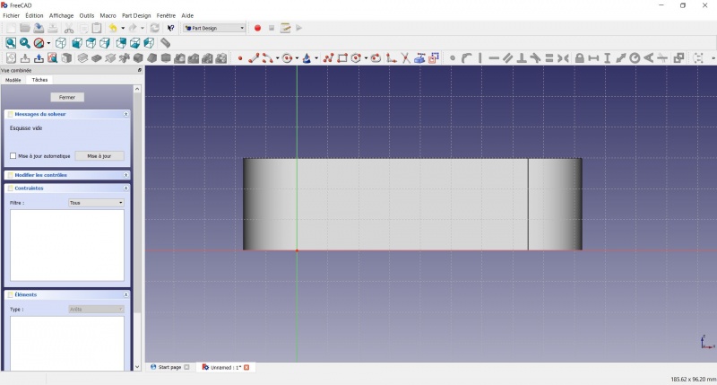
- Draw an
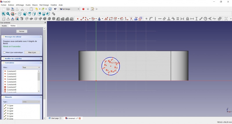
 Hexagon
- Click to place the center
- Move to define the radius
- Click to set
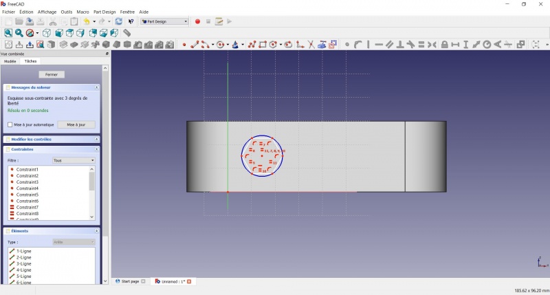
- Click on an edge of the hexagon
- Click on
 Horizontal
- Click on the center of the hexagon
- Click on the horizontal line of the XY plane
- Click on
 Length
 - A dialog prompts you to set a dimension. Enter 15mm, click OK.
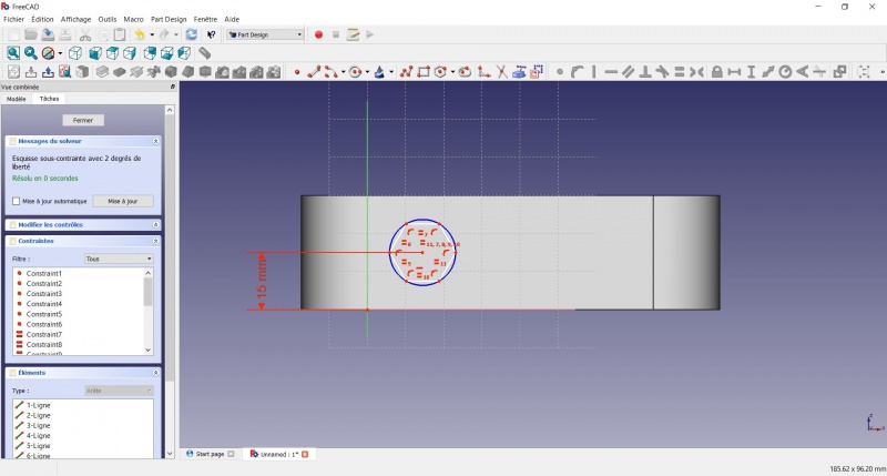
- Click on the center of the hexagon
- Click on the vertical of the XY plane
- Click on
 Length
 - A dialog prompts you to set a dimension. Enter 10mm, click OK.
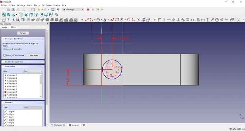
- Click on the blue circle of the hexagon
- Click on
 Radius
 - A dialog prompts you to set a dimension. Enter 8mm, click OK.
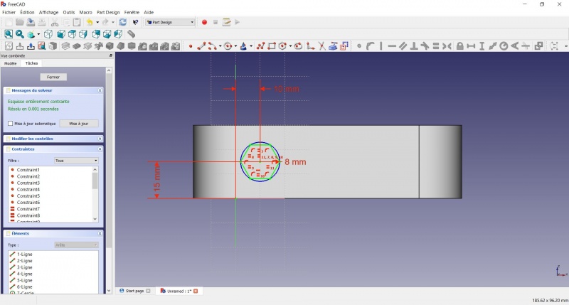
- To leave the sketch, click either on the "Close" button on the left, or the
 icon in the toolbar, or press ESC.
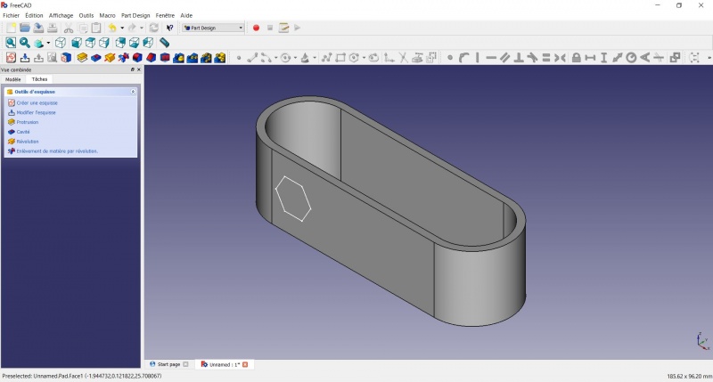
Create a hole
- Click on
 Axonometric among the standard views, to better see what will happen.
 - Click on
 Pocket.
 - Select to the first in the dropdown menu and click OK.
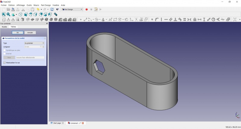
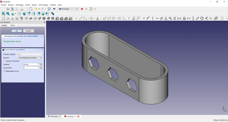
Linear repetition
- In the Combo View on the left, select the tree view instead of the contextual task menu, click on the pocket feature.
- Click on
 LinearPattern.
 - Set the length at 55mm and occurencies at 3, then click OK.
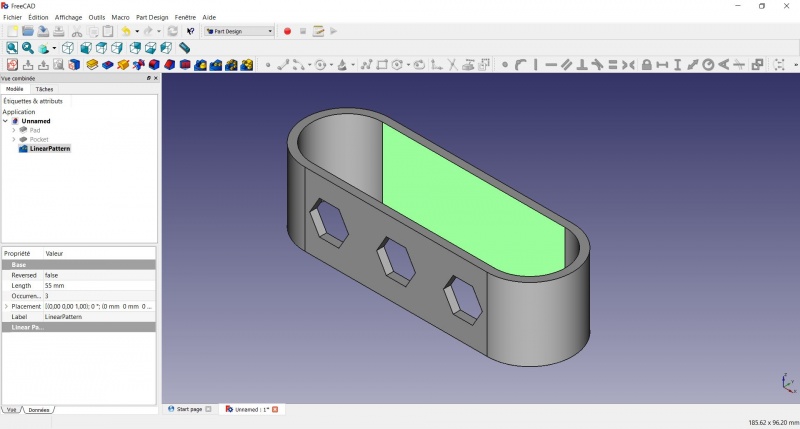
Create a sketch on it
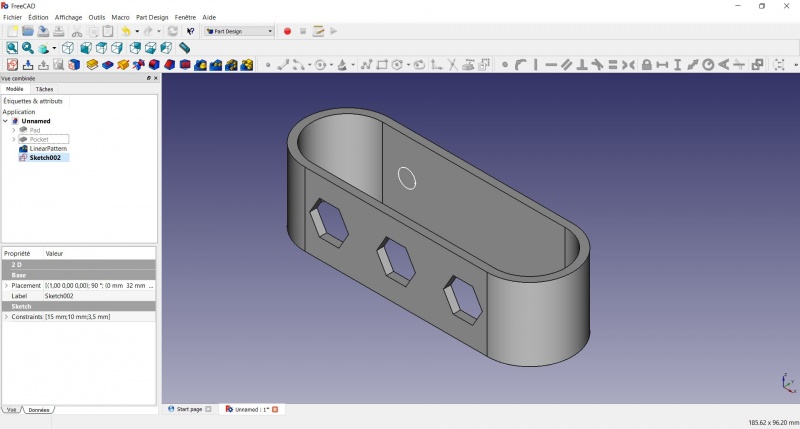
- Select the inner face
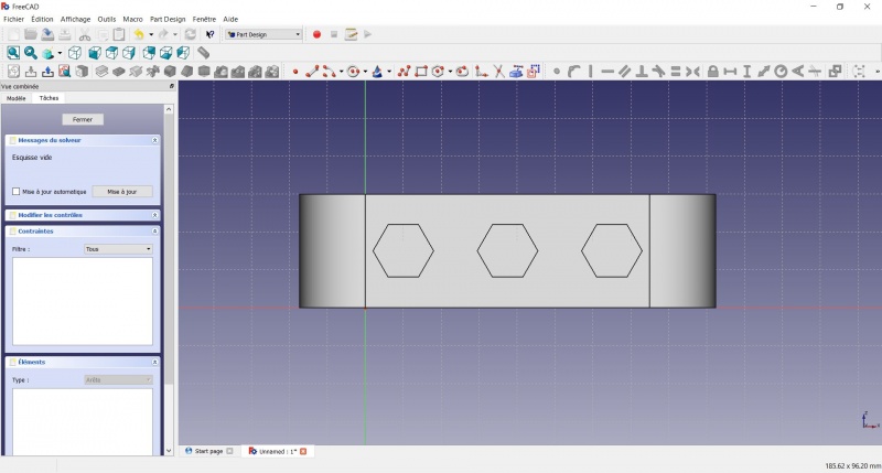
- Click on
 Circle, click to place the center, move the pointer and click to define the radius.
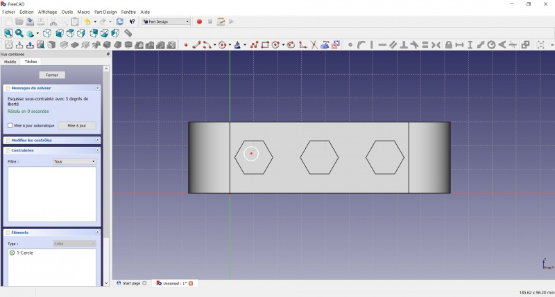
- Click on the center of the circle
- Click on the horizontal line of the XY plane
- Click on
 Length
 - A dialog prompts you to set a dimension. Enter 15mm, click OK.
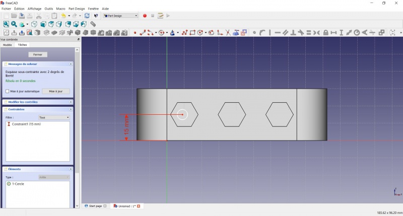
- Click on the center of the circle
- Click on the vertical of the XY plane
- Click on
 Length
 - A dialog prompts you to set a dimension. Enter 10mm, click OK.
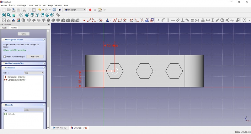
- Click on the circle
- Click on
 Radius
 - A dialog prompts you to set a dimension. Enter 3.5mm, click OK.
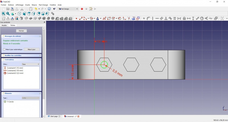
- To leave the sketch, click either on the "Close" button on the left, or the
 icon in the toolbar, or press ESC.
Create a pad
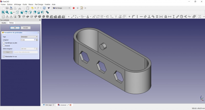
- Click on
 Axonometric among the standard views, to better see what will happen.
 - Click on
 Pad.
Pad. - Enter 4mm and click OK.
Linear repetition
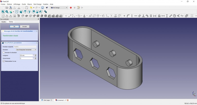
- In the Combo View on the left, select the tree view instead of the contextual task menu, click on the pad feature.
- Click on
 LinearPattern.
 - Set the length at 55mm and occurencies at 3, then click OK.
Draft
- Select the side of each round pads
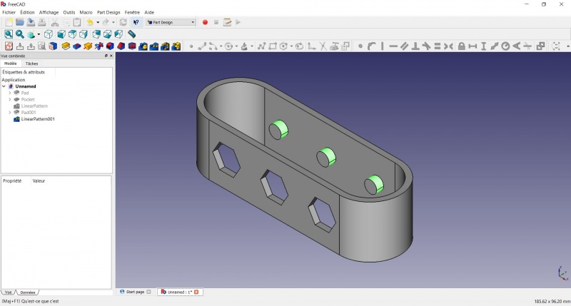
- Click on
 Draft.
 - Set the draft angle at 40°.
- Click on "Neutral plane" and select the face on which the sketch is drawn.
- Tick "Invert the draft direction".
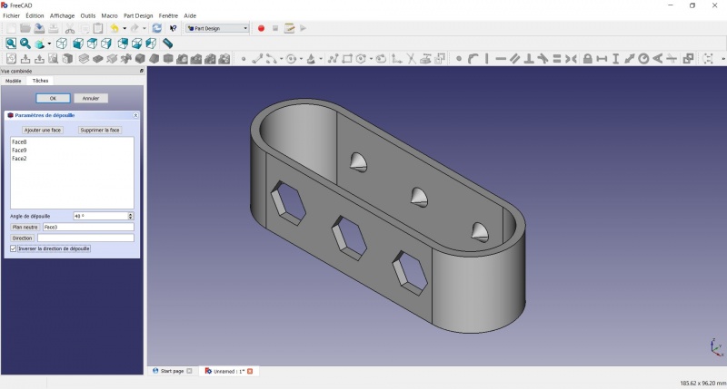
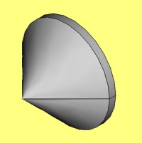
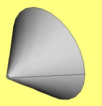
We could have used a chamfer to do something similar, but the draft is more appropriate in this case.
Chamfer = left / Draft = right
Finitions
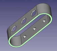
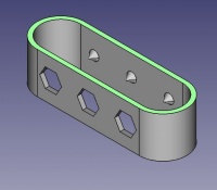
- Holding CTRL select the bottom and top faces.
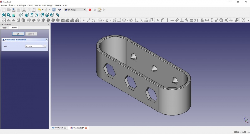
Perfect !
Export as a .STL
- In the Combo View on the left, select the tree view instead of the contextual task menu, click on the last feature (the chamfer).
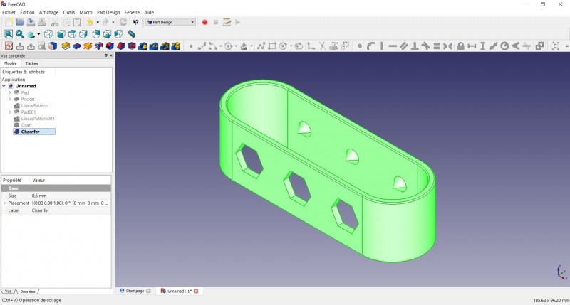
- Now you can select "Export..." from the File menu at the top left, and select the file format .STL.
- Print it instead of the first version or to replace it if it eventually broke ;-)
