Sketcher Tutorial/pl: Difference between revisions
(Created page with "Przedstawione powyżej trójkąty mają białe linie. Świadczy to o tym, że na szkicu pozostały pewne stopnie swobody. Można to sprawdzić ciągnąc za niektóre linie lub...") |
(Created page with "W trójkącie równoramiennym brakuje ustawienia długości linii bazowej i może się on swobodnie poruszać i obracać w płaszczyźnie rysunkowej szkicownika.") |
||
| Line 67: | Line 67: | ||
Przedstawione powyżej trójkąty mają białe linie. Świadczy to o tym, że na szkicu pozostały pewne stopnie swobody. Można to sprawdzić ciągnąc za niektóre linie lub punkty. Jeśli linia lub punkt porusza się, nie jest on w pełni związany. Szkic bez pozostawionych stopni swobody zmienia kolor na zielony. |
Przedstawione powyżej trójkąty mają białe linie. Świadczy to o tym, że na szkicu pozostały pewne stopnie swobody. Można to sprawdzić ciągnąc za niektóre linie lub punkty. Jeśli linia lub punkt porusza się, nie jest on w pełni związany. Szkic bez pozostawionych stopni swobody zmienia kolor na zielony. |
||
W trójkącie równoramiennym brakuje ustawienia długości linii bazowej i może się on swobodnie poruszać i obracać w płaszczyźnie rysunkowej szkicownika. |
|||
The isoscele triangle is missing the length setting for the base line and it can move and rotate freely in the sketcher drawing plane. |
|||
If the triangle properties are defined, it still needed to be fixed in the drawing plane. The sketcher drawing plane has a coordinate system. The origin of the coordinate system is visible as the red dot in the center of the pink x-axis and light-green y-axis. The easiest way to fix it, is selecting a vertex and clicking at [[Image:Constraint_Lock.png|32px]]. This adds a horizontal and a vertical distance from the vertex to the origin of the coordinate system. The triangle may still have an degree of freedom for rotation. So one sides needs a horizontal or vertical constraint or an defined angle to one of the coordinate system axes. The next picture shows a fully constraint sketch. All lines and vertices have now a green color. |
If the triangle properties are defined, it still needed to be fixed in the drawing plane. The sketcher drawing plane has a coordinate system. The origin of the coordinate system is visible as the red dot in the center of the pink x-axis and light-green y-axis. The easiest way to fix it, is selecting a vertex and clicking at [[Image:Constraint_Lock.png|32px]]. This adds a horizontal and a vertical distance from the vertex to the origin of the coordinate system. The triangle may still have an degree of freedom for rotation. So one sides needs a horizontal or vertical constraint or an defined angle to one of the coordinate system axes. The next picture shows a fully constraint sketch. All lines and vertices have now a green color. |
||
Revision as of 19:14, 31 January 2020
| Temat |
|---|
| Sketcher |
| Poziom trudności |
| Początkujący |
| Czas wykonania |
| dowolny |
| Autorzy |
| Ulrich |
| Wersja FreeCAD |
| Pliki z przykładami |
| brak |
| Zobacz również |
| - |
Wprowadzenie
Szkicownik jest narzędziem do generowania obiektów 2D do wykorzystania w projektowaniu części. Szkicownik różni się od tradycyjnych narzędzi rysunkowych. Sposobem na pokazanie tej różnicy jest konstrukcja trójkąta. Trójkąt jest w pełni zdefiniowany przez 3 wartości, które mogą być dowolne z następującej listy: długość boku, kąt, wysokość, powierzchnia. Jedynym wyjątkiem są trzy kąty, które nie definiują rozmiarów.
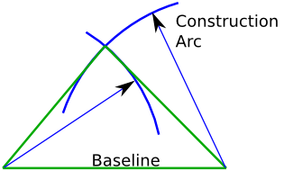
Aby zbudować trójkąt z 3 odcinków w tradycyjny sposób, należy wykonać następujące czynności:
- narysować linię bazową,
- wykonać dwa łuki o promieniu wyznaczonym przez pozostałe dwie długości boków lub obliczyć współrzędne trzeciego punktu,
- narysować brakujące dwa boki od punktów końcowych linii podstawowej do punktu przecięcia dwóch kół lub obliczonego wierzchołka.
Strona Wiki: Trójkąt pokazuje zbiór formuł do obliczania brakujących informacji w celu narysowania trójkąta z minimum informacji. Są one potrzebne, jeśli trójkąt musi być zdefiniowany za pomocą wstępnie obliczonych współrzędnych.
Sketcher jest inny. Formuły i powyższe konstrukcje pomocnicze nie są potrzebne. Aby zrozumieć tę różnicę, najlepiej skonstruować trójkąt samodzielnie.
Pierwszy szkic: trójkąt
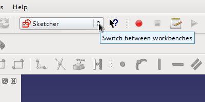
Do wykonania szkicu potrzebny jest otwarty dokument. Gdy nie ma otwartego dokumentu, zostanie utworzony nowy, poprzez kliknięcie na ![]() . Należy wybrać stanowisko pracy Sketcher:
. Należy wybrać stanowisko pracy Sketcher:
Nowy szkic zostanie utworzony po kliknięciu na ![]() . Pojawi się okno dialogowe, w którym można wybrać orientację nowego szkicu w przestrzeni 3D. W tym przypadku nie ma to znaczenia, więc można potwierdzić płaszczyznę X-HY. Nowy pusty szkic zostanie utworzony i otwarty w trybie edycji. Zostanie wyświetlona siatka z układem współrzędnych z czerwonym punktem początku.
. Pojawi się okno dialogowe, w którym można wybrać orientację nowego szkicu w przestrzeni 3D. W tym przypadku nie ma to znaczenia, więc można potwierdzić płaszczyznę X-HY. Nowy pusty szkic zostanie utworzony i otwarty w trybie edycji. Zostanie wyświetlona siatka z układem współrzędnych z czerwonym punktem początku.
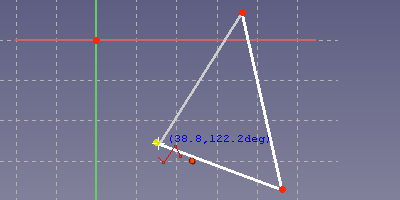
W programie Sketcher można narysować dowolny trójkąt za pomocą narzędzia ![]() polilinia i określić jego właściwości w kolejnym kroku. Każde kliknięcie w płaszczyźnie rysowania ustawia wierzchołek. Trójkąt musi zostać zamknięty. Tak więc w przypadku ostatniej linii potrzebne jest kliknięcie na pierwszy utworzony wierzchołek. Przed kliknięciem, w pobliżu kursora myszki powinien być widoczny czerwony punkt.
polilinia i określić jego właściwości w kolejnym kroku. Każde kliknięcie w płaszczyźnie rysowania ustawia wierzchołek. Trójkąt musi zostać zamknięty. Tak więc w przypadku ostatniej linii potrzebne jest kliknięcie na pierwszy utworzony wierzchołek. Przed kliknięciem, w pobliżu kursora myszki powinien być widoczny czerwony punkt.
Stworzony trójkąt jest elastyczny. Punkt można chwycić myszką i przeciągnąć dookoła. Boki trójkąta podążają za wierzchołkiem. To samo można zrobić z linią.
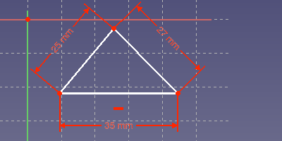
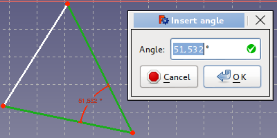
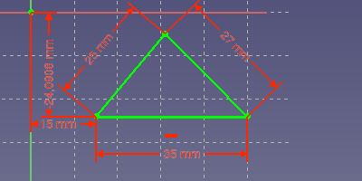
Każda długość boku może być teraz łatwo zdefiniowana poprzez zaznaczenie go myszką: zaznaczony element zmienia kolor na zielony. Po kliknięciu na narzędzie definiujące długość ![]() otwiera się okno dialogowe i można wprowadzić żądaną długość. Poniższy rysunek przedstawia trójkąt o długości poszczególnych boków ustawionej na 35mm, 27mm i 25mm. Linia podstawowa została ustawiona poziomo poprzez jej zaznaczenie i kliknięcie na narzędzie wiązanie poziome
otwiera się okno dialogowe i można wprowadzić żądaną długość. Poniższy rysunek przedstawia trójkąt o długości poszczególnych boków ustawionej na 35mm, 27mm i 25mm. Linia podstawowa została ustawiona poziomo poprzez jej zaznaczenie i kliknięcie na narzędzie wiązanie poziome ![]() .
.
Te definicje długości nazywane są wiązaniami. Wiązania są używane do określenia stałej konstrukcji na podstawie danych wejściowych o elastycznej geometrii. Szkicownik podaje wszystkie wiązania potrzebne do zdefiniowania dowolnego rodzaju trójkąta. Tylko obszar nie może być użyty do zdefiniowania jednego z nich. Tak więc utworzony trójkąt może zostać przedefiniowany przez zmianę wartości wiązania lub przez usunięcie wiązania i dodanie innych. Tutaj znajduje się lista trójkątów o innych określonych właściwościach. Nie jest problemem przekształcenie właśnie utworzonego trójkąta w jeden z nich.
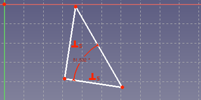
- Podano jeden lub dwa kąty: Należy wybrać dwa boki trójkąta. Kliknięcie na
 otwiera okno dialogowe do ustalenia wartości tego kąta.
- Prawidłowy trójkąt: Trzeba wybrać dwa boki trójkąta. Kliknięcie na przycisk
 ustawia kąt prosty pomiędzy dwoma bokami.
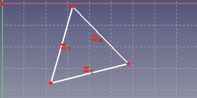
- Równoboczny: Jeden bok musi być ustawiony na określoną długość. Następnie należy wybrać wszystkie boki. Kliknięcie przycisku
 definiuje dwa ograniczenia równej długości w celu nadania wszystkim bokom tej samej długości.
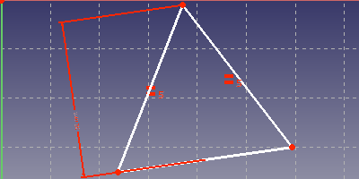
- Trójkąt równoramienny (dwie identyczne długości) o danej wysokości: Wybierz najpierw dwa boki o tej samej długości. Kliknięcie na
 ustawia równość między dwoma bokami. Następnie wybierz linię bazową i wierzchołek i kliknij na narzędzie 32px długości.
Wiązania można wybrać klikając na symbol lub klikając na liście wiązań. Można je usunąć lub też zmodyfikować wartość po dwukrotnym kliknięciu. Dany trójkąt może być później zmieniony na inny typ trójkąta poprzez edycję lub zmianę wiązania. Szkicownik jest również elementem metody parametrycznego modelowania w programie FreeCAD. To, co zostało stworzone, może być łatwo zmienione w późniejszym czasie, jeśli np. potrzebny jest jakiś wariant projektu.
Przedstawione powyżej trójkąty mają białe linie. Świadczy to o tym, że na szkicu pozostały pewne stopnie swobody. Można to sprawdzić ciągnąc za niektóre linie lub punkty. Jeśli linia lub punkt porusza się, nie jest on w pełni związany. Szkic bez pozostawionych stopni swobody zmienia kolor na zielony.
W trójkącie równoramiennym brakuje ustawienia długości linii bazowej i może się on swobodnie poruszać i obracać w płaszczyźnie rysunkowej szkicownika.
If the triangle properties are defined, it still needed to be fixed in the drawing plane. The sketcher drawing plane has a coordinate system. The origin of the coordinate system is visible as the red dot in the center of the pink x-axis and light-green y-axis. The easiest way to fix it, is selecting a vertex and clicking at File:Constraint Lock.png. This adds a horizontal and a vertical distance from the vertex to the origin of the coordinate system. The triangle may still have an degree of freedom for rotation. So one sides needs a horizontal or vertical constraint or an defined angle to one of the coordinate system axes. The next picture shows a fully constraint sketch. All lines and vertices have now a green color.
More about Constraints
The sketcher does not know the triangle formulas from the wikipedia. Instead it sets up a system of equation for the 2-dimensional coordinates based on the given constraints. This system of equations is then solved numerically.
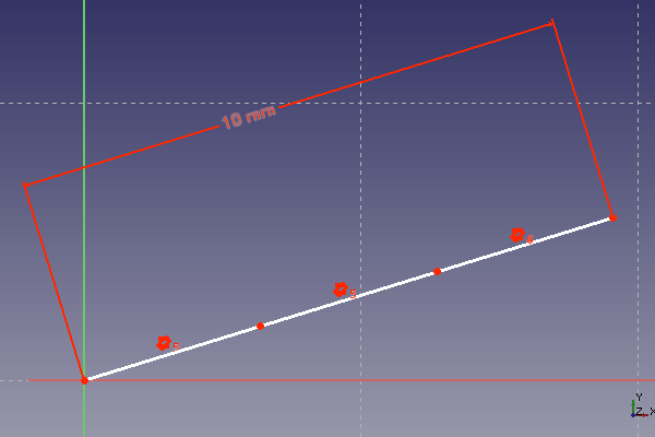
In this way a wide variety of geometric problem can be solved. But there is also a disadvantage. If the set of equations has multiple solutions, we may get something totally different from what we expect. This is especially annoying, if the same design should be used for different dimensions. The typical symptom is, that after a change of a length constraint, the sketch flips to something totally different. A simple example is the division of a distance into three equal partitions. The following picture shows three lines in a row with equality and parallel constraint set. The total distance is set to 10 mm.
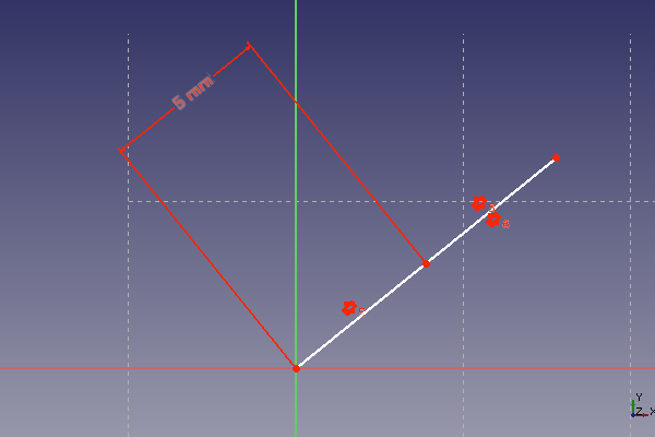
This works well, as long as only larger distances are put in. When the distance is reduced above a certain ratio, the lines are folding together. So we do not get any more a third of the given distance but the distance itself or two third of it. Some lines of our row have changed their orientation. This gives still a valid solution for the set of constraints, but is not what was intended. So following image of the same sketch shows this. The length constraint was set to 1000 mm and then reduced to 5 mm.
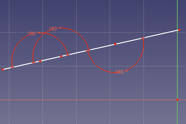
The solution is to define an angle of 180° between the partition lines as replacement of the parallel constraint. The 180°-constraint has only one solution. The sketch is now robust against large changes of the distance. It has to be said, that also a 0°-constraint serves for the same purpose, where appropriate.
The 180°-constraint is a solution for a lot of problems. Some older versions of FreeCAD have problems to show the 180°-constraint in the sketcher plane. In most of the cases the 180°-arc is not shown as expected in the sketcher drawing plane. This is a known issue for FreeCAD before version 14.3613.
In case of several incremental dimensions in a straight line, it may be advisable to draw a zig-zag-line first and then set the 180°-constraints. This helps, not forgetting one, or setting one twice.
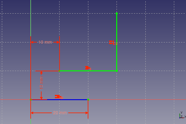
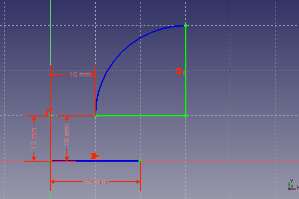
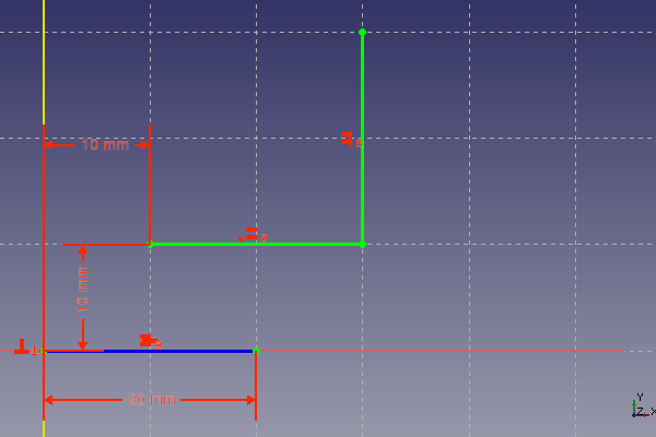
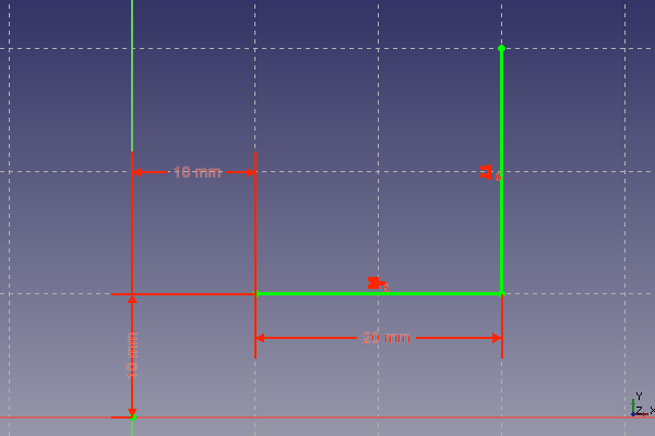
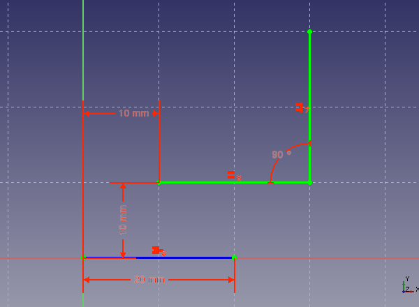
The following table shows some constraints combinations for the definition of a simple elbow. The combination was tested by enlarging the 10 mm length horizontal dimension to greater values until the elbow flips its orientation. The table documents for each shown constraint combination the changed length where the flipping occurs.
| Constraints Combination | Remarks |
|---|---|
|
Definition of length: Equality constraint for definition of length | |
|
Definition of length: Equality constraint for definition of vertical length, arc for definition of horizontal length. | |
|
Definition of length: Equality constraint for definition of length | |
|
Definition of length: Horizontal length defined with the general length constraint. Equality constraint for definition of vertical length. | |
|
Definition of length: Equality constraint for definition of length |
The test showed the following: larger changes of dimension constraints may cause a flipping of some lines of the sketch due to multiple solutions of the underlying system of equations. The only constraints that do preserve the orientation of the elements they are applied to, are the angle constraint and the horizontal and vertical dimension constraints. The differences between the other constraints regarding maintaining orientation are minor.
Recommendation: Use angle constraints and horizontal and vertical dimension constraints at critical places in order to make a sketch robust against dimension changes.
Problematic combination of constraints
Sometimes two or more constraints define the same property. An example can be made of two connected lines, where the connection point is the center point of a symmetry constraint for the endpoints of the lines. Those lines now have equal length and are parallel. All this is the consequence of the symmetry constraint.
What happens, if those two lines already have an equality constraint and a parallel constraint and the symmetry constraint is added too? Now the parallel property is defined by two constraints and the equal length is also defined by two constraints. In principle the underlying system of equations should have a solution. But there may be numerical problems. This can be tested by trying to move the lines. In most cases the lines are frozen, even if the sketcher still reports several degrees of freedom.
The above case shows a problem that seems to be difficult to solve for the sketcher programmers. So the user has to take care, to avoid such situations. Sketches with redundant constraints do behave unexpected and problematic. Symptoms of those redundant constraints are the above frozen state or reported redundant constraints after modifying a different object in the sketch.
In general the sketcher gives a warning, when redundant constraints are detected. But this detection mechanism seems not to work in all cases. When the problem is recognized, it can be avoided by just deleting the redundant constraints. Sometimes it is necessary to choose a different combination of constraints.
The following cases are sources for redundant constraints:
- An equality constraint for two radii of the same arc
- An symmetry constraint for two radii of the same arc
- A symmetry constraint in combination with parallel, equality and or perpendicular constraints
A different problematic case are parallels with an intersection point in infinity. It is possible to set a 180°-constraint for two parallel lines without an intersection point. This is not recommended. An angle to an other line or axis should be used instead.
A different problem is the change of orientation of angles. This can happen if, angle changes above 180° are made. Doing this in smaller steps avoid the problem.
Construction Lines - Step by Step Example
In the first part was shown, that helper constructions are not necessary for the triangle. But nevertheless the sketcher provides construction geometry, which is useful for more complex problems. Any line can be converted to a construction line with the ![]() button. The construction lines are shown in the sketch as blue lines. They can be used for constraints in the same way as other lines, but are not shown and not used when the sketch is closed.
button. The construction lines are shown in the sketch as blue lines. They can be used for constraints in the same way as other lines, but are not shown and not used when the sketch is closed.
Giving the task to make a rectangle with the side length having the golden ratio. Wikipedia shows how to construct two lines with a length ratio of the golden ratio.
The sketcher is a perfect tool to construct a rectangle with the golden ratio for the side length. The size of the rectangle can be later changed without making a new construction. The construction steps for the golden ratio according to Wikipedia are:
- Having a line segment AB, construct a perpendicular BC at point B, with BC half the length of AB. Draw the hypotenuse AC.
- Draw an arc with center C and radius BC. This arc intersects the hypotenuse AC at point D.
- Draw an arc with center A and radius AD. This arc intersects the original line segment AB at point S. Point S divides the original segment AB into line segments AS and SB with lengths in the golden ratio.
Here is a step by step explanation, how this can be done.
- Make a new sketch as explained at the triangle example.
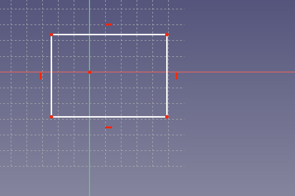
- Draw a rectangle in the sketch. Use the button
 The following picture shows the rectangle. FreeCAD did add horizontal and vertical constraints to the rectangle. This rectangle can not be rotated.
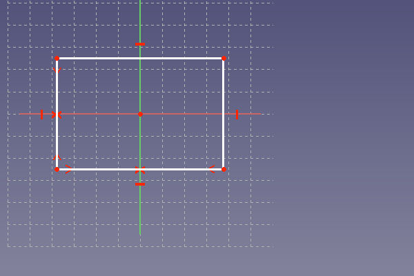
The rectangle should stay in the center of the coordinate system. To achieve this, a symmetry constraint is added to a horizontal line. This is done by selecting first the two vertices of the horizontal line and then the vertical axis of the coordinate system. The symmetry constraint is added by clicking on the button ![]() . The same is done for a vertical line, but instead now the horizontal axis is selected as symmetry axis. The picture below shows the result. The rectangle stays now at the center and can only be resized but not moved.
. The same is done for a vertical line, but instead now the horizontal axis is selected as symmetry axis. The picture below shows the result. The rectangle stays now at the center and can only be resized but not moved.
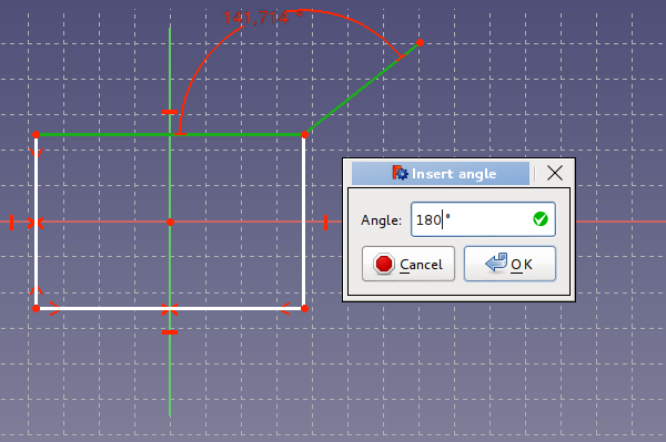
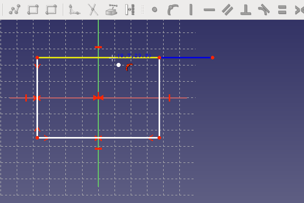
This was the preparation for the rectangle. The top horizontal line should be the distance AS of the golden ration construction. An additional line is needed to represent the SB-distance. It is drawn a little bit skewed as shown below. This avoids the auto-constraining to horizontal. This line should instead be constrained later with a 180°-angle, in order to avoid the existence of multiple solutions to the constructed constrain-combination. If the line is drawn with an horizontal constrained, the sketcher will complain later at adding the 180°-angle constrained. The horizontal constrained has to be removed in such a case. The picture shows how to add an angle-constraint by selecting two lines and clicking at ![]() . After adding a line, it is often advisable to drag at the line with the mouse. This will easily show, if a line is not attached to the other drawn elements. If a line is not connected right to the other lines, problems may arise in later steps of the part construction.
. After adding a line, it is often advisable to drag at the line with the mouse. This will easily show, if a line is not attached to the other drawn elements. If a line is not connected right to the other lines, problems may arise in later steps of the part construction.
The last line is not part of the rectangle. It is therefore necessary to convert it into a construction line. Selecting the line and clicking at the ![]() button does the conversion.
button does the conversion.
The line has now a blue color as visible below. The recipe from Wikipedia for the golden ratio requires a line half of the distance AB. In order to get a reference point for this, an additional vertex is set at the line with the ![]() tool. This is shown below.
tool. This is shown below.
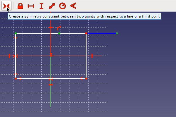
The reference point should stay at the center of the distance AB. This will be achieved by selecting first the two endpoints of the distance AB and third selecting the center point. When all three points are selected in the right sequence, the symmetry constraint can be set at clicking at the ![]() button, as shown below.
button, as shown below.
The Picture below shows already the second side BC of the construction triangle. This line was drawn as described above and converted to a construction line. This line must have a vertical constraint as visible in the picture. This can be easily achieved by drawing the line nearly vertical. If the line is nearly vertical a vertical constraint symbol is shown and set by the Sketcher when finishing the line at this state.
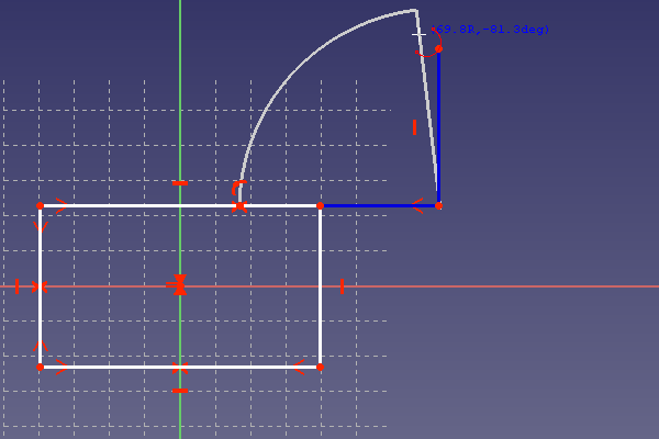
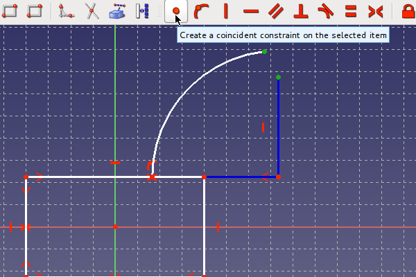
The line BC must have half of the length of AB. There is only a reference point available for this purpose, so the equality constraint can not be used. The equality constraint would need a line with this length as reference, which is not available in the construction. Therefore the classical arc is used to define the length BC. The picture below shows the drawing of the arc. The arc-tool [[Image:|24px]] is used. First the center point is set at B. The point should be visible beneath the arc-tool at clicking at B. Often the arc-tool has not has to be not directly over the target point but a little beneath, in order to get the coincidence point visible. Second the radius of the arc is defined by setting the next point at the reference point. The last point of the arc is set in the neighborhood of the point C. It is important, that the first two points are fixed to C and the center point. This should be tested with dragging at the arc after finishing it.
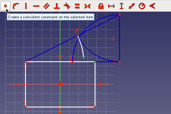
In order to define the length of BC, the line must end at the arc. This will be done by setting a coincidence constraint between the last arc point and the C point as shown below. Both points have to be selected and the create a coincidence button ![]() has to be clicked.
has to be clicked.
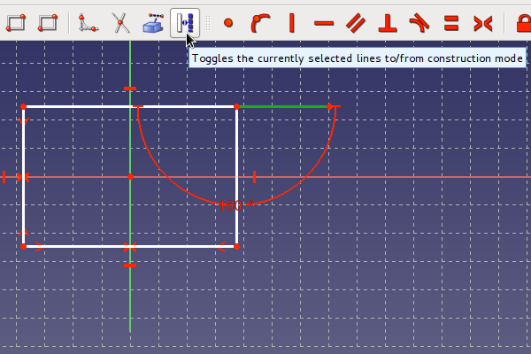
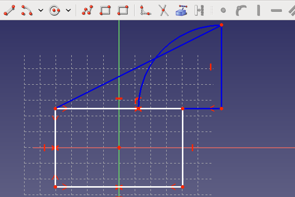
The next picture shows the ready triangle. The hypotenuse AC is already drawn and converted to a construction line.
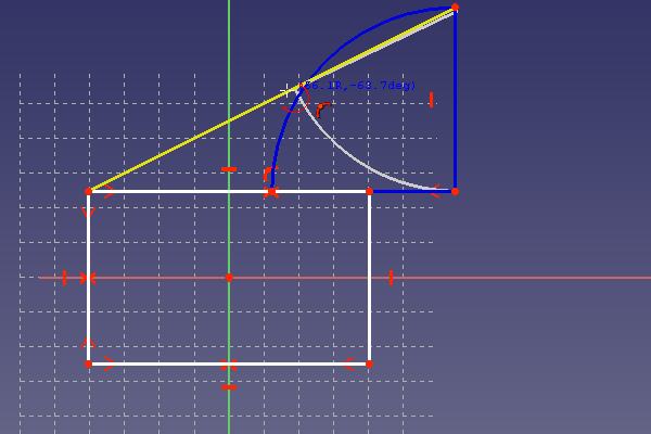
Now step 2 of the Wikipedia recipe has to be constructed. A second arc has to be drawn with the center point at C and the starting point at B. The last point should be end at the hypotenuse as shown in the picture below.
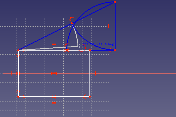
The drawn arc was converted to a construction line. Now step 3 of the Wikipedia recipe starts with drawing the last arc as shown in the picture below. The radius of this arc has to be defined with the above constructed point on the hypotenuse. The last point will usually not end at a corner of the rectangle. But this is not a problem, as it will be fixed later. The last point may set as shown below.
Now the final step has to be made, in order to made the horizontal line of the rectangle equal to the distance AS. This is shown below by setting a coincidence constraint between the end of the last arc and the corner of the rectangle.
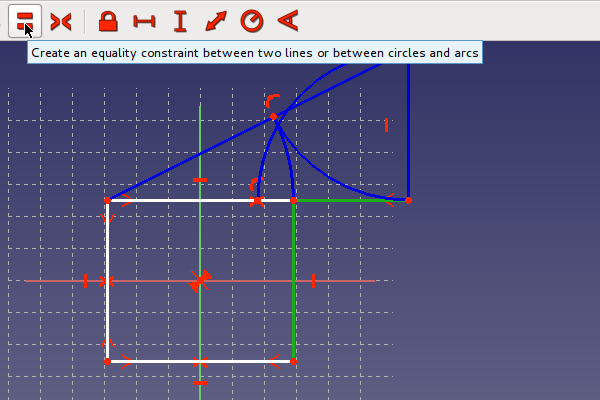
Now the vertical line has to be made the length of the distance SC. Setting an equality constraint by selecting the button ![]() as shown below, will do this.
as shown below, will do this.
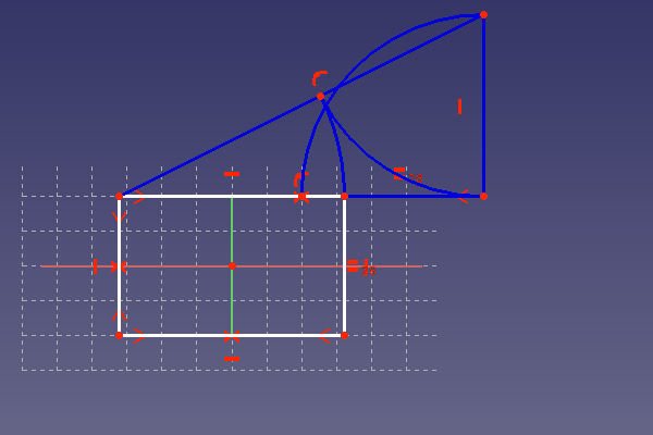
The next picture shows the rectangle with a side length ratio equal to the golden ratio. The rectangle should have only left one degree of freedom. So at dragging at it, it should only change its size but not move. If a certain size of one side is needed, a length constraint can be added to this side. Other wise the sketch is ready and can be closed. Only a rectangle should than be visible in the FreeCAD window.
Exercise: resilient sketch
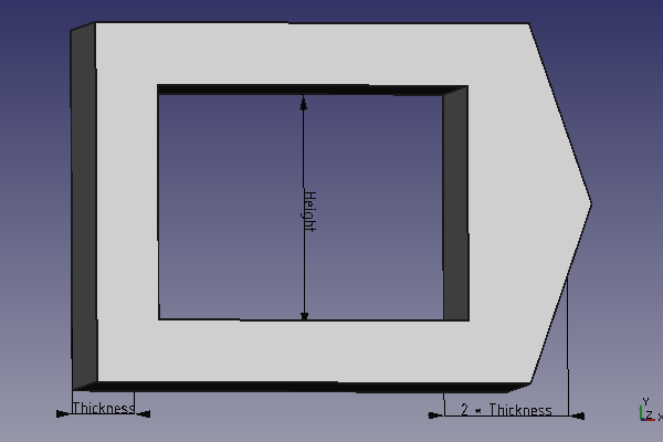
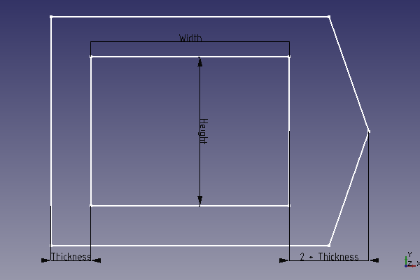
The above example introduced construction lines. Now some important things to make resilient sketches are discussed. Here is an exercise to get some practice at working with the sketcher. The goal is to make a sketch for something like a special frame as shown below.
Powinny istnieć tylko trzy wymiary potrzebne do zdefiniowania konstrukcji. Aby ułatwić zmianę wymiarów, można zmienić nazwę wprowadzonych ograniczeń na coś zapadającego w pamięć. Wystarczy zaznaczyć ograniczenie w widoku listy i wcisnąć <F2>. Wiązanie można nazwać na przykład Grubość. Poniższy rysunek przedstawia wymiary. Szczyt po prawej stronie powinien mieć dwa razy większą grubość niż ściana.
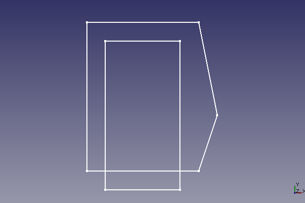
Szkic powinien wyglądać zgodnie z założeniami również po zmianie kluczowych wymiarów np. na 2000mm i z powrotem na 30. Aby osiągnąć ten cel, może być konieczne użycie wiązań kątów w wybranych miejscach. Poniższy rysunek przedstawia szkic, który nie był odporny na takie zmiany. Nie nadaje się on teraz do użytku. Aby odzyskać oryginalny stan, można użyć przycisku cofania File:Edit-undo.png.
Powyższy szkic nie nadaje się do zastosowania w przypadku Środowiska pracy Part Design. Tylko profil bez przecinających się linii jest dopuszczalny. Linie konstrukcyjne mogą się przecinać. Nie są one używane do tworzenia brył.
Jednym z głównych zastosowań Szkicownika jest budowa części w obrębie stanowiska pracy Part-Design. Istniejąca już geometria może być wykorzystywana podobnie jak linie konstrukcyjne. Ponieważ ten poradnik skupia się bardziej na podstawowej funkcjonalności szkicownika, spójrz tutaj na wykorzystanie zewnętrznej geometrii: Szkicownik zewnętrzny.
