SheetMetal Workbench: Difference between revisions
Renatorivo (talk | contribs) No edit summary |
Renatorivo (talk | contribs) No edit summary |
||
| Line 53: | Line 53: | ||
* Files: |
* Files: |
||
* Report bugs: Please report bugs at https://github.com/shaise/FreeCAD_SheetMetal/issues |
* Report bugs: Please report bugs at https://github.com/shaise/FreeCAD_SheetMetal/issues |
||
==Sheet Metal Tutorial== |
|||
This workbench is used to manufacture sheet metal parts of all thickness, welded folded and to provide their fold or "blank". |
|||
Does not allow to obtain stamped parts. |
|||
===Presentation of the workbench=== |
|||
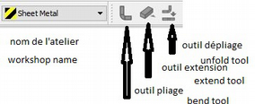
After downloading the extension and install, open it. |
|||
[[Image:sm1.png]] |
|||
===1st operation=== |
|||
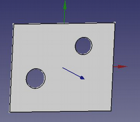
* Get the base: use either the workbenches "part" or "draft", make 1 sketch that will contain all holes and any cuts, extrude this base to the thickness of the sheet. |
|||
* Bear in mind that the edges will always be in addition as well as the folding radii. |
|||
[[Image:sm2.png]] |
|||
===2nd operation=== |
|||
* Open the Sheet_metal workbench. |
|||
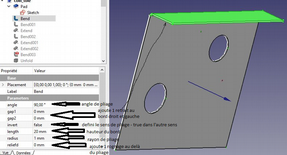
* Select 1 thickness of the edge (edge) of the base plate and click on the "bend" tool 90° default bend angle can be changed from 0 to 90°. |
|||
* Edge height is 10mm by default, editable from 0.1 to xxxmm. |
|||
* Bending radius is by default equal to thickness, editable from 0.1 to xxmm (never put 0). |
|||
* Gap1, gap2 is the withdrawal of the folded edge from the corner of the base (0 accept). |
|||
* Invert default: false folds to Z +, true to ZReliefd cuts the corner between the fold and the base (inactive if gap = 0). |
|||
* Reliefw adds 1 slot between the crop and the edge (inactive if reliefd = 0). |
|||
[[Image:sm3.png]] |
|||
Repeat as many times as there are sides to bend. <br /> |
|||
Folding 1 return with use of "extend".<br /> |
|||
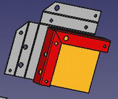
[[Image:sm4a.png]] |
|||
To add 1 back repeat the same operation by selecting the thickness of the concerned edge. <br /> |
|||
To reduce the space between the 2 edges, use "extends". <br /> |
|||
Select the thickness and specify the length to add. <br /> |
|||
Note that if the extension of the 1st edge is made before the fold of the return, it will not be taken into account, if 1 identical fold is added to the extension, it will appear correct but the unfolding will not be done. <br /> |
|||
Folding of 1 2nd edge: <br /> |
|||
Now we must separate the 2 edges otherwise they will merge and unfolding will be impossible. <br /> |
|||
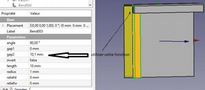
* 1st method: make 1 withdrawal of 1 edge. |
|||
** Give 1 value slightly greater than gap1 (or gap2), at zero there is still fusion. |
|||
* 2nd method make 1 cut at 45 ° see further, use this tool. |
|||
[[Image:sm5a.png]] |
|||
===Unfolding=== |
|||
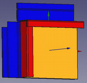
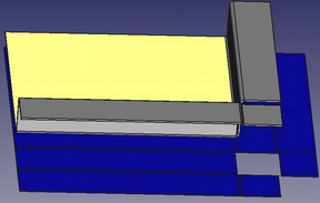
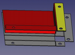
Choose 1 reference face (here the orange face) and click on the button in the toolbar. <br /> |
|||
We obtain the blue part of which it is enough to modify the values X, Y, or Z to see it in totality. <br /> |
|||
[[Image:sm6.png]] |
|||
===Cut the flaps at 45°=== |
|||
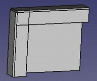
After folding the flaps without having made a withdrawal, the shape thus appears. |
|||
[[Image:sm7a.png]] |
|||
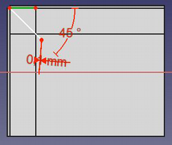
To do it must split at 45 ° (or following the bisector flaps are unequal width). <br /> |
|||
* Create 1 new skit related to the common part of the 2 flaps. |
|||
* Create 1 linked stop by selecting the outer edge of the "hinge". |
|||
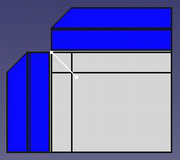
* Draw 1 triangle whose top is constrained at the end, oriented 1 side at 45 °, give the small side 1 minimum width (0.1mm is enough), and make 1 pocket. <br /> |
|||
Be careful not to scratch the "hinge" where the nakedness of bound the tip of the triangle at the edge of the fold line. |
|||
[[Image:sm8a.png]] |
|||
===Unfolding=== |
|||
[[Image:sm9.png]] |
|||
Piercing edges and flaps. <br /> |
|||
Make these holes and cuts after folding and before unfolding. <br /> |
|||
Always take care not to "scratch" the fold lines. <br /> |
|||
[[Image:sm10.png]] |
|||
Make wired flaps. <br /> |
|||
Make 1 fold on the edge of the side, at 45 ° of 0.1mm long, then 1 other reverse at 45 ° of the length of the contiguous flap, then extend the opposite side, it will pass over and they will not be merged. <br /> |
|||
[[Image:sm11.png]] |
|||
Special case of this same pierced edge. <br /> |
|||
In this particular case, unfolding only works by choosing the yellow face as a reference. <br /> |
|||
[[Image:sm12.png]] |
|||
Special case hole straddling the folds. <br /> |
|||
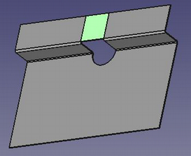
Previously it is said several times that it is not necessary to cut the folding lines. <br /> |
|||
How to do ? <br /> |
|||
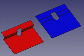
[[Image:sm13.png]] |
|||
* Make the base with its half-round hole and make the 2 half-sided and the 2 half-folds separately. |
|||
* Then make 1 extension on 1 of the sides of the width of the opening minus 0.1mm, the 2 edges thus remain separated. |
|||
* Then on this extension (in green) draw the contour of the cut and make 1 pocket |
|||
* The result is the red piece above, and the unfolding works, stays the line that separated the 2 edges previously |
|||
[[Image:sm14.png]] |
|||
==Other useful links== |
==Other useful links== |
||
Revision as of 21:25, 23 October 2017
Introduction
A simple sheet metal workbench for FreeCad
References
- Author:
- Folding tools: Copyright 2015 by Shai Seger
- Unfolding tool: Copyright 2014 by Ulrich Brammer
- Home page: http://theseger.com/projects/2015/06/sheet-metal-addon-for-freecad/
- Source code on github: https://github.com/shaise/FreeCAD_SheetMetal
Tools
Detailed description here
Toolbar
File:SheetMetal-menu-orizz.png
Bend: extends a wall from a side face of metal sheet
Extrude: extrude a face along normanl
Unfold: flatten folded sheet metal object
Other
- File:SheetMetal SheetMetal.png SheetMetal icon
Installation
Automatic installation
See Installing
From GitHub
Prerequisites
- FreeCAD v0.16
Installing the extension
- Download the extension: SheetMetal_V0.0.17
- Extract this zip file into the Mod directory under the FreeCAD installation path. (on Windows it’s something like “C:\Program Files\FreeCAD 0.16\Mod”)
- You should now see a new directory under Mod: SheetMetal.
Links to SheetMetal WB
- Workbench Wiki: http://theseger.com/projects/2015/06/sheet-metal-addon-for-freecad/
- FreeCAD Wiki: Sheet metal unfolder
- FreeCAD Forum: http://forum.freecadweb.org/viewtopic.php?t=11303
- Tutorials: https://forum.freecadweb.org/viewtopic.php?f=3&t=25002
- Videos:
- Files:
- Report bugs: Please report bugs at https://github.com/shaise/FreeCAD_SheetMetal/issues
Sheet Metal Tutorial
This workbench is used to manufacture sheet metal parts of all thickness, welded folded and to provide their fold or "blank".
Does not allow to obtain stamped parts.
Presentation of the workbench
After downloading the extension and install, open it.
1st operation
- Get the base: use either the workbenches "part" or "draft", make 1 sketch that will contain all holes and any cuts, extrude this base to the thickness of the sheet.
- Bear in mind that the edges will always be in addition as well as the folding radii.
2nd operation
- Open the Sheet_metal workbench.
- Select 1 thickness of the edge (edge) of the base plate and click on the "bend" tool 90° default bend angle can be changed from 0 to 90°.
- Edge height is 10mm by default, editable from 0.1 to xxxmm.
- Bending radius is by default equal to thickness, editable from 0.1 to xxmm (never put 0).
- Gap1, gap2 is the withdrawal of the folded edge from the corner of the base (0 accept).
- Invert default: false folds to Z +, true to ZReliefd cuts the corner between the fold and the base (inactive if gap = 0).
- Reliefw adds 1 slot between the crop and the edge (inactive if reliefd = 0).
Repeat as many times as there are sides to bend.
Folding 1 return with use of "extend".
To add 1 back repeat the same operation by selecting the thickness of the concerned edge.
To reduce the space between the 2 edges, use "extends".
Select the thickness and specify the length to add.
Note that if the extension of the 1st edge is made before the fold of the return, it will not be taken into account, if 1 identical fold is added to the extension, it will appear correct but the unfolding will not be done.
Folding of 1 2nd edge:
Now we must separate the 2 edges otherwise they will merge and unfolding will be impossible.
- 1st method: make 1 withdrawal of 1 edge.
- Give 1 value slightly greater than gap1 (or gap2), at zero there is still fusion.
- 2nd method make 1 cut at 45 ° see further, use this tool.
Unfolding
Choose 1 reference face (here the orange face) and click on the button in the toolbar.
We obtain the blue part of which it is enough to modify the values X, Y, or Z to see it in totality.
Cut the flaps at 45°
After folding the flaps without having made a withdrawal, the shape thus appears.
To do it must split at 45 ° (or following the bisector flaps are unequal width).
- Create 1 new skit related to the common part of the 2 flaps.
- Create 1 linked stop by selecting the outer edge of the "hinge".
- Draw 1 triangle whose top is constrained at the end, oriented 1 side at 45 °, give the small side 1 minimum width (0.1mm is enough), and make 1 pocket.
Be careful not to scratch the "hinge" where the nakedness of bound the tip of the triangle at the edge of the fold line.
Unfolding
Piercing edges and flaps.
Make these holes and cuts after folding and before unfolding.
Always take care not to "scratch" the fold lines.
Make wired flaps.
Make 1 fold on the edge of the side, at 45 ° of 0.1mm long, then 1 other reverse at 45 ° of the length of the contiguous flap, then extend the opposite side, it will pass over and they will not be merged.
Special case of this same pierced edge.
In this particular case, unfolding only works by choosing the yellow face as a reference.
Special case hole straddling the folds.
Previously it is said several times that it is not necessary to cut the folding lines.
How to do ?
- Make the base with its half-round hole and make the 2 half-sided and the 2 half-folds separately.
- Then make 1 extension on 1 of the sides of the width of the opening minus 0.1mm, the 2 edges thus remain separated.
- Then on this extension (in green) draw the contour of the cut and make 1 pocket
- The result is the red piece above, and the unfolding works, stays the line that separated the 2 edges previously
Other useful links
- DevWorkbenches: List of workbenches in development.
- Macros recipes
- FreeCAD Download
- FreeCAD Community Portal
