PartDesign : Tutoriel
| Thème |
|---|
| Sketcher |
| Niveau |
| Beginner |
| Temps d'exécution estimé |
| 15 minutes |
| Auteurs |
| Drei |
| Version de FreeCAD |
| 0.16 or above |
| Fichiers exemples |
| Voir aussi |
| None |
Introduction
Ce tutoriel a pour but d'initier le lecteur à utilisation de l' atelier PartDesign.
File:PartDesign tutorial result.png
Prérequis
- FreeCAD version 0.16 ou supérieure
- Avoir lu le tutoriel sur les esquisses
Procédure
Créer une forme géométrique 3D
L'objectif de l' atelier PartDesign est de permettre à l'utilisateur de créer des formes géométriques dans un espace 3D, pour répondre à un certain besoin. Ainsi , sont mis à disposition des outils pour faire des esquisses et les convertir en objets 3D.
Il existe deux outils de base pour y parvenir: ![]() Pad et
Pad et ![]() Revolution. À coté de leur équivalent de substitution (
Revolution. À coté de leur équivalent de substitution (![]() Pocket et
Pocket et ![]() Groove) Ils permettent de faire la plupart des actions usuelles utilisées dans cet atelier.
Groove) Ils permettent de faire la plupart des actions usuelles utilisées dans cet atelier.
- Aller sur l'atelier PartDesign
- Sélectionner l'esquisse crée dans le tutoriel sur les esquisse
- Sélectionner
 Pad
Pad - Renseigner une distance de 5mm
- Sélectionnez Ok
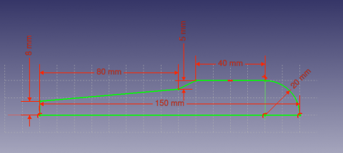
Une autre manière de créer des formes géométriques 3D est avec l'outil ![]() Revolution .
Revolution .
- Créez une esquisse d'après l'image ci-dessus
- Sélectionnez
 Revolution
 - Renseignez un angle de 360°
Outils d'enlèvement de matière
Nous allons commence par créer une esquisse avec la forme que nous voulons enlever.
- Sélectionnez la face supérieure du pad
- Sélectionnez
 New sketch
 - Sélectionnez
 External Geometry
 - Approchez vous du bord du pad, un arc devrait apparaître en surbrillance
- Sélectionnez l'arc. Un arc de couleur différente devrait apparaître dans l'esquisse
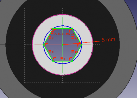
- Créez un cercle centré sur le même point que l'arc, et renseignez un rayon de 5 mm
When a 3D element has been created it is possible to create references to it within a sketch.
- Select
 External Geometry.
 - Approach the element that you wish to reference, the edge of a Pad for example.
- Click on it
- New elements of a different color should appear on the sketch in the location of the feature you wish to reference.
Après cela, nous allons utiliser l'outil poche.
- Sélectionnez l'esquisse
- Sélectionnez
 Poche
Poche - Réglez la distance sur À travers tout
Pattern Features
Recall the extruded profile that was created at the start of the tutorial.
- Select the top face of the object
- Create a new Sketch
- Create reference geometry linked to the top arm of the figure
- Create a circle constrained to the center of the reference arc
- Set its radius to 3 mm
- Pocket the sketch through all the workpiece
Instead of creating a circle for each hole in the sketch, we will introduce the concept of Pattern Features. These tools operate by replicating a feature in the workpiece that has already been created and that we wish to reproduce in a linear or circular arrangement. We will use a combination of Linear and Polar pattern features simulatneously to obtain the final workpiece.
- Select the Pockt feature that we just created in the Tree View
- Select
 MultiTransform
In the Combo View we are now asked to introduce the Transformations that we desire. Notice that in the MultiTransform parameters menu we see that FreeCAD has identified the Pocket as the Original feature and a second box requests us to Right click it to introduce the pattern features.
- Right click the box
- Select Add Linear Pattern
- Set the Direction to Vertical Sketch Axis
- Set length to 10 mm
- Leave occurrences at 2
- Click OK
- Right click the box again to add a Polar Pattern. Notice that the 3D view has now added the linear pattern.
- Set occurrences to 5
- Click OK twice
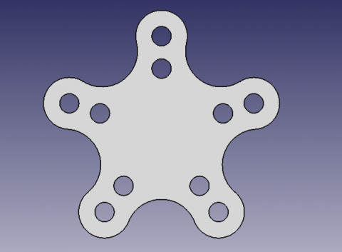
After completing this task you should have the following result.
If not, re-edit the MultiTransform operation by double clicking on it in the Tree View. Check both pattern features to detect necessary modifications, such as the Axis and if the Direction needs to be reversed.
We are now finished with the basic workflow for the PartDesign Workbench.


