PartDesign Bearingholder Tutorial I/pl: Difference between revisions
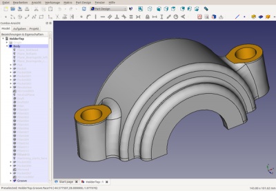
(Created page with "thumb|400px|right|text-top|Główna geometria górnej części uchwytu. Twoja część powinna teraz wyglądać jak na zdjęciu po prawej stronie. Zwróć uwagę, jak różne wycięcia łączą się, tworząc prawie jednolitą grubość ścianki, co ułatwi odlewanie i zmniejszy ryzyko powstawania porów. <br clear=all>") |
(Created page with "thumb|400px|right|text-top|Szkic ze schematem, gdzie będą znajdować się śruby. Teraz pozostaje tylko stworzyć materiał, przez który przejdą śruby. Można pokusić się o naszkicowanie ich jako okręgu, a następnie ich obłożenie, ale spowoduje to kłopoty przy późniejszej próbie nałożenia na nie szkicu ''(zakładam, że jest to słaby punkt OpenCascade)''. Aby ominąć te problemy, lepiej jest utworzyć szkic z uwzględnieniem...") |
||
| Line 80: | Line 80: | ||
<br clear=all> |
<br clear=all> |
||
[[Image:HolderTop1-8.jpg|thumb|400px|right|text-top| |
[[Image:HolderTop1-8.jpg|thumb|400px|right|text-top|Szkic ze schematem, gdzie będą znajdować się śruby.]] |
||
Teraz pozostaje tylko stworzyć materiał, przez który przejdą śruby. Można pokusić się o naszkicowanie ich jako okręgu, a następnie ich obłożenie, ale spowoduje to kłopoty przy późniejszej próbie nałożenia na nie szkicu ''(zakładam, że jest to słaby punkt OpenCascade)''. Aby ominąć te problemy, lepiej jest utworzyć szkic z uwzględnieniem kąta szkicu, a następnie obrócić go o 360°. |
|||
Now all that remains is to create some material for the bolts to go through. You might be tempted to sketch these as a circle and then pad them, but this will head you for trouble when you try to put the draft onto them later (I assume that is a weakness of OpenCascade). So to circumvent the problems, it is better to create a sketch with the draft angle included and then rotate it through 360 degrees. |
|||
Here again the skeleton planes come in useful. You will need the bolt axis plane and the bolt head plane as external geometry. Then, create a straight line for the rotation axis and make sure it is constrained to the bolt axis plane reference. Toggle it to be construction geometry. Then, sketch the rest of the contour. The important dimensions are the machining allowance at the top and bottom and the radius of 12mm: 7mm for the hole radius + 5mm wall thickness. |
Here again the skeleton planes come in useful. You will need the bolt axis plane and the bolt head plane as external geometry. Then, create a straight line for the rotation axis and make sure it is constrained to the bolt axis plane reference. Toggle it to be construction geometry. Then, sketch the rest of the contour. The important dimensions are the machining allowance at the top and bottom and the radius of 12mm: 7mm for the hole radius + 5mm wall thickness. |
||
Revision as of 18:58, 3 February 2024
| Temat |
|---|
| Modelowanie |
| Poziom trudności |
| Użytkownik zaawansowany |
| Czas wykonania |
| nieokreślony |
| Autorzy |
| NormandC |
| Wersja FreeCAD |
| 0.19.23300 lub nowszy |
| Pliki z przykładami |
| brak |
| Zobacz również |
| - |
Cel w skrócie
Celem tego poradnika jest zapoznanie użytkownika z dwoma różnymi przebiegami pracy dla tworzenia części odlewanej z pochyleniami i zaokrągleniami. W zależności od tego, z jakich innych programów CAD korzystałeś, jeden lub drugi może być ci znany. Jako przykład roboczy będziemy modelować prostą oprawkę łożyska.
To jest pierwsza część poradnika. Wykorzysta on coś, co można nazwać przepływem pracy pojedynczej zawartości, używając (prostszej) górnej części uchwytu jako przykładu.
Oczywiście, aby przejść przez ten poradnik należy aktywować środowisko pracy Projekt Części.
Moją wersję części stworzonej za pomocą tego poradnika można znaleźć [tutaj]. Plik nie jest już dostępny, nowy zostanie udostępniony w późniejszym terminie.
Założenia projektowe
Oprawka powinna być w stanie utrzymać łożysko o średnicy 90 mm i szerokości do 33 mm (np. DIN 630 typ 2308). Łożysko wymaga kołnierza o wysokości co najmniej 4,5 mm w oprawie (i na wale). Górna część oprawy zostanie przykręcona do dolnej za pomocą dwóch śrub 12 mm. Po obu stronach łożyska powinien znajdować się rowek umożliwiający zamocowanie standardowego pierścienia uszczelniającego wał DIN 3760: 38x55x7 lub 40x55x7 z jednej strony i 50x68x8 z drugiej strony.
Uchwyt będzie odlewem piaskowym o minimalnej grubości ścianki 5 mm, kącie zanurzenia 2° i minimalnym promieniu zaokrąglenia 3 mm.
Konfigurowanie geometrii szkieletu
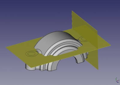
Idea geometrii szkieletowej polega na uchwyceniu podstawowych wymiarów projektu w pojedynczym elemencie odniesienia (np. płaszczyźnie lub osi). Gdy wymiar projektu ulegnie zmianie, wszystko, co należy zrobić, to zmienić cechę szkieletu. Jeśli model jest dobrze zbudowany, wszystkie jego cechy zostaną ponownie obliczone, aby odzwierciedlić zmianę projektu. Zmniejsza to niebezpieczeństwo, że w złożonym modelu, w którym podstawowe wymiary projektowe są używane w wielu miejscach, zapomnisz je gdzieś zmienić.
Alternatywą dla geometrii szkieletowej jest posiadanie tabeli podstawowych wymiarów projektowych, która przypisuje nazwę symboliczną do każdego wymiaru, a następnie używa nazwy symbolicznej wszędzie tam, gdzie wymiary są wymagane do zbudowania modelu. FreeCAD nie pozwala jeszcze na takie podejście.
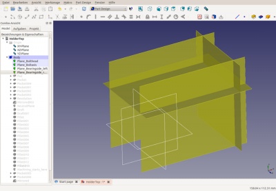
W przypadku oprawy łożyska dwa najważniejsze wymiary konstrukcyjne to odległość między śrubami (która ogranicza rozmiar łożyska, które można zastosować) oraz wysokość łbów śrub. Wybrane wymiary to
- Odległość między śrubami: Promień łożyska (45) + grubość ścianki (5) plus promień otworu na śrubę (7) = 57 mm, więc płaszczyzna pionowa będzie przesunięta o 57 mm od płaszczyzny YZ. Aby utworzyć tę płaszczyznę odniesienia, wybierz płaszczyznę YZ, a następnie wybierz opcję utworzenia nowej płaszczyzny odniesienia. Wprowadź przesunięcie w oknie dialogowym, które zostanie otwarte
- Wysokość łbów śrub: Została ona wybrana jako przesunięcie o 28 mm w stosunku do płaszczyzny XZ.
Dla wygody można utworzyć dwie dodatkowe płaszczyzny odniesienia, aby odzwierciedlić ilość materiału, który musi zostać odcięty od boków oprawy łożyska. Są one przesunięte o +22 i -22 względem płaszczyzny XY.
Zaleca się nadawanie jasnych nazw geometrii szkieletu. W większości przypadków będziesz chciał wyłączyć widoczność płaszczyzn odniesienia, ponieważ zaśmiecają one widok, a jeśli płaszczyzny mają przyjazne nazwy, możesz po prostu wybrać je według nazwy zamiast z widoku.
Geometria bryły
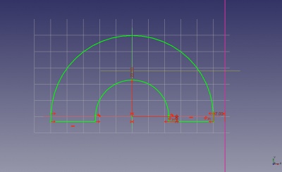
Teraz nadszedł czas, aby rozpocząć tworzenie prawdziwej geometrii. Szkic pierwszego wyciągnięcia jest pokazany po prawej stronie. Jest on umieszczony na płaszczyźnie XY. Istnieją tylko trzy wymiary: Promień wewnętrzny (22,5 mm), naddatek na obróbkę (3 mm) u podstawy jako przesunięcie względem płaszczyzny XZ oraz odległość od płaszczyzny odniesienia reprezentującej oś śruby (7 mm). Oznacza to, że jeśli później przesuniesz płaszczyznę odniesienia, wyciągnięcie automatycznie dostosuje swój promień zewnętrzny. Pamiętaj, że zanim będziesz mógł użyć płaszczyzny odniesienia do wymiarowania, musisz wprowadzić ją jako geometrię zewnętrzną do szkicownika.
Prawdopodobnie zastanawiasz się, dlaczego na dole każdego łuku znajduje się mały prosty odcinek. Segment ten zapewnia, że kąt pochylenia łuków będzie wynosił 2 stopnie. Może to wyglądać na dużo pracy dla bardzo małej korzyści, ale wiele programów CAD (a może kiedyś FreeCAD) ma narzędzia, które podświetlają model bryłowy w różnych kolorach i natychmiast pokazują wszystkie powierzchnie, w których kąt pochylenia nie jest prawidłowy. Nie chcesz, aby stało się to z twoim modelem, zwłaszcza po nałożeniu wielu zaokrągleń!
Po wykonaniu szkicu (co jest nieco trudne ze względu na 2-stopniowe linie styczne), po prostu umieść go symetrycznie względem płaszczyzny szkicu o długości 62 mm: 34 mm na łożysko, 2x 9 mm na pierścienie uszczelniające, 2x 5 mm na grubość ścianki.
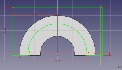
Następnie chcemy odciąć trochę materiału w miejscu, w którym znajdują się pierścienie uszczelniające, ponieważ ich średnica zewnętrzna jest znacznie mniejsza niż średnica łożyska. Najprostszym sposobem na utworzenie szkiców jest zaznaczenie szkicu wyciągnięcia, a następnie wybranie opcji "Powiel zaznaczenie" z menu edycji. Następnie można ponownie zmapować szkic do boku wyciągnięcia i zmodyfikować go tak, jak pokazano na rysunku.
Jedyne dwa ważne wymiary na szkicu to 3 mm naddatku na obróbkę na dole i średnica wewnętrzna 78 mm: 68 mm na zewnętrzną średnicę pierścienia uszczelniającego + 2x 5 mm grubości ścianki. Ponieważ pierścień uszczelniający po drugiej stronie będzie miał tylko 55 mm średnicy, wycięcie może mieć tutaj 65 mm.
Po utworzeniu szkicu, wsuń go do płaszczyzny odniesienia oznaczającej stronę łożyska plus 5 mm grubości ścianki. Jeśli kiedykolwiek będziesz chciał zmodyfikować oprawę, aby była w stanie pomieścić szersze łożyska, wszystko, co musisz zrobić, to zmienić wymiar tych płaszczyzn odniesienia, a głębokość wycięcia podąży za tym.
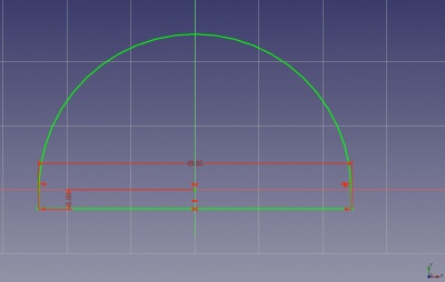
Aby zmniejszyć ilość wymaganej obróbki, chcemy również odciąć trochę materiału wewnątrz uchwytu. Ponownie, powielenie szkicu pierwszego wyciągnięcia jest wygodne. Nie trzeba go nawet przekształcać. Ponownie, jedynymi ważnymi wymiarami są naddatek na obróbkę (3 mm) i średnice zewnętrzne: 84 mm dla miejsca, w którym będzie znajdować się łożysko (90 mm - 2x naddatek na obróbkę), 49 mm dla mniejszego pierścienia uszczelniającego (55 mm - 2x 3 mm) i 62 mm dla większego pierścienia uszczelniającego.
Po utworzeniu szkiców należy je włożyć do kieszeni: Symetrycznie 28mm na wycięcie pod łożysko (34mm - 2x naddatek na obróbkę) i jednostronnie 23mm na wycięcia pod pierścienie uszczelniające: 34 mm / 2 dla połowy szerokości łożyska + 9 mm dla pierścieni uszczelniających - naddatek na obróbkę 3 mm.
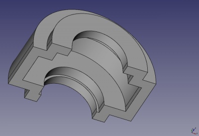
Twoja część powinna teraz wyglądać jak na zdjęciu po prawej stronie. Zwróć uwagę, jak różne wycięcia łączą się, tworząc prawie jednolitą grubość ścianki, co ułatwi odlewanie i zmniejszy ryzyko powstawania porów.
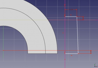
Teraz pozostaje tylko stworzyć materiał, przez który przejdą śruby. Można pokusić się o naszkicowanie ich jako okręgu, a następnie ich obłożenie, ale spowoduje to kłopoty przy późniejszej próbie nałożenia na nie szkicu (zakładam, że jest to słaby punkt OpenCascade). Aby ominąć te problemy, lepiej jest utworzyć szkic z uwzględnieniem kąta szkicu, a następnie obrócić go o 360°.
Here again the skeleton planes come in useful. You will need the bolt axis plane and the bolt head plane as external geometry. Then, create a straight line for the rotation axis and make sure it is constrained to the bolt axis plane reference. Toggle it to be construction geometry. Then, sketch the rest of the contour. The important dimensions are the machining allowance at the top and bottom and the radius of 12mm: 7mm for the hole radius + 5mm wall thickness.
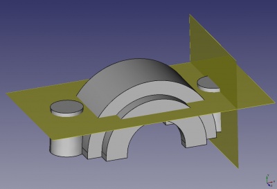
Create a revolution feature from the sketch and then mirror it on the YZ-plane. This is all the solid geometry we need to model. The rest is draft and fillets.
Applying draft to the side faces
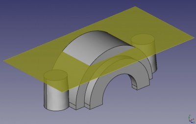
The next step is to apply drafts on all faces. Its important to consider the location of the neutral plane, that is, the plane which the face is "rotated" around. If we choose as neutral plane the bottom of the holder, then we will have a problem with the wall thickness in the top part of the holder. Therefore, we create a datum plane at an offset of 40mm from the XZ plane as a compromise between the top of the holder becoming to thin and the bottom becoming to wide.
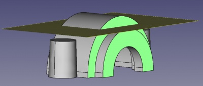
To put draft on a face, select this face and create the draft feature. You can then select more faces to apply the draft on. If you have a large part, it is advisable to draft only one face at a time. This means that if you change the geometry and a draft fails, only this one feature will fail, whereas if you put all faces in one draft feature, then the whole feature might fail because of one face failing. For a small part like the bearing holder, its sufficient to create two draft features: One for the four outside faces, and one for the inside faces.
The dialog will force you to select a neutral plane before completing. You can leave the pull direction empty, in this case it will be normal to the neutral plane. Don't forget to set the draft angle to 2 degrees.
Filleting the holder
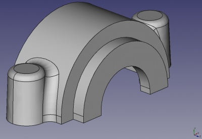
We can now fillet the part. The picture shows the first set of fillets. Start with the small circular fillets and make them 4mm radius. Even though 3mm would be enough as per specification of the part, a radius of 4mm means that after machining 1mm of the fillet is left, reducing the sharp edge produced by the machining. The large fillets are 6mm radius to help spread the force from the bolts into the rest of the part. It would be nice to make this radius even larger, but unfortunately OpenCascade can't handle overlapping fillets yet.
As with drafts, in a complex part you should fillet only one edge at a time to avoid unnecessary failures if the base geometry changes.
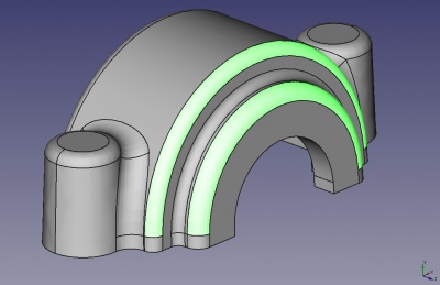
The rest of the fillets are simply 3mm radius. Looking at the picture on the right, the two highlighted fillets could actually be filleted with 5mm to achieve a more uniform wall thickness for the casting. After machining, the minimum wall thickness of 5mm would still be maintained. But again the fact that OpenCascade can't handle overlapping fillets prevents us from doing this for the inner of the two highlighted fillets.
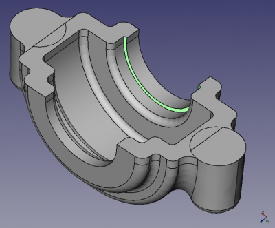
Filleting the inside of the part presents us with a difficulty that cannot be solved with the current tools in the PartDesign workbench. The highlighted edge cannot be filleted at all, again because the rounds would overlap. This could be worked around by creating a sweep instead of a fillet, except that sweeps are not implemented in PartDesign yet. For the time being, we are forced to leave the edge as it is.

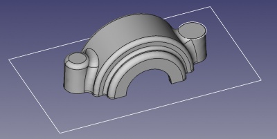
The picture on the right shows the finished part in the state it will be before machining (except for the one edge that is impossible to fillet). You will notice that one edge that runs around the whole part has been left unfilleted on purpose. This is the edge where the bottom and the top of the mould meet. Here, no fillet is possible (and none is required anyway).
Machining
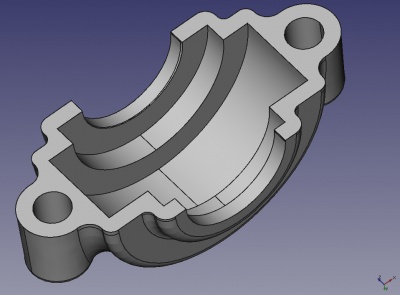
Now we can cut away the material that will be machined off the raw cast part. This is very easy with the skeleton geometry defined. The idea is to create all machining features (Pockets and Grooves) using datum features only. This means they will be totally independent of the solid geometry of the bearing holder, which gives us some big advantages:
- No matter how you change the solid geometry, the features for the machining can never fail.
- You can create the machining geometry before finalizing the solid, which gives you useful visual feedback.
- If you move the skeleton datum planes, then both the solid geometry and the machining will adapt automatically.
- If you make a mistake in your solid geometry, the machining will still be in the correct position, and very likely the mistake will become glaringly obvious (e.g. a wall thickness becoming 2mm instead of 5mm). Whereas if you reference the machining to the solid geometry, it will adapt to the error in the solid and e.g. maintain the 5mm wall thickness, just in the same wrong location as the solid is.
Before starting on the machining geometry, I like to place a datum point in the tree and name it something like "Machining_starts_here". This is useful if you want to switch between the raw and the machined state of the part because you can see at a glance where to move the insert point to get the raw state.
To machine the bottom of the holder, just sketch a large rectangle on the XZ plane and pocket it. For the top, sketch a circle on the datum plane defining the bolt head location, and then mirror the pocket on the YZ plane. In the same way, create a pocket for the hole which the bolt will go through and mirror it. To machine the inside of the holder, create a sketch on the YZ plane and groove it.

Once you have done the machining, you can have a nice visual effect by colouring all the machined faces so that you can see at one glance which parts are raw casting and which are machined after casting.
Final notes
We have modelled the bearing holder top with the dimensions it will have after casting. To create the casting mould, you need to apply shrinkage to your part because after casting, when the hot metal cools down, it will shrink by a few percent (depending on the material). Usually it is best to leave the application of shrinkage to the foundry making the part because they have the required special knowledge. They should also tell you if your part has problematic areas, e.g. very thick walls suddenly joining to very thin sections without a properly tapered section between them.