Macro Draft Circle 3 Points 3D/de: Difference between revisions
mNo edit summary |
(Updating to match new version of source page) |
||
| Line 17: | Line 17: | ||
[[File:Macro_Draft_Circle_3_Points_3D.png|480px]] |
[[File:Macro_Draft_Circle_3_Points_3D.png|480px]] |
||
<div class="mw-translate-fuzzy"> |
|||
==Verwenden Sie== |
==Verwenden Sie== |
||
Wählen Sie 3 Punkte oder Formulare in der 3D-Ansicht aus und führen Sie das Makro aus. <br /> |
Wählen Sie 3 Punkte oder Formulare in der 3D-Ansicht aus und führen Sie das Makro aus. <br /> |
||
Wenn die Form eine Linie ist, ist die Koordinate der Mittelpunkt der Linie. |
Wenn die Form eine Linie ist, ist die Koordinate der Mittelpunkt der Linie. |
||
</div> |
|||
==Grenzen== |
==Grenzen== |
||
| Line 31: | Line 33: | ||
'''Macro_Draft_Circle_3_Points_3D.FCMacro''' |
'''Macro_Draft_Circle_3_Points_3D.FCMacro''' |
||
{{ |
{{MacroCode|code= |
||
# -*- coding: utf-8 -*- |
# -*- coding: utf-8 -*- |
||
# Create a circle from 3 points selected on the X, Y, Z map |
# Create a circle from 3 points selected on the X, Y, Z map |
||
Revision as of 10:16, 23 May 2020
| Beschreibung |
|---|
| Erzeugt einen Kreis aus 3 ausgewählten Punkten im Raum. Versionsmakro : 01.00 Datum der letzten Änderung : 2013-03-16 FreeCAD version : All Herunterladen : ToolBar Icon Autor: galou_breizh |
| Autor |
| galou_breizh |
| Herunterladen |
| ToolBar Icon |
| Links |
| Makros Rezepte Wie installiere ich Makros So passen Sie Symbolleisten an |
| Macro-Version |
| 01.00 |
| Datum der letzten Änderung |
| 2013-03-16 |
| FreeCAD-Version(s) |
| All |
| Standardverknüpfung |
| None |
| Siehe auch |
| None |
Beschreibung
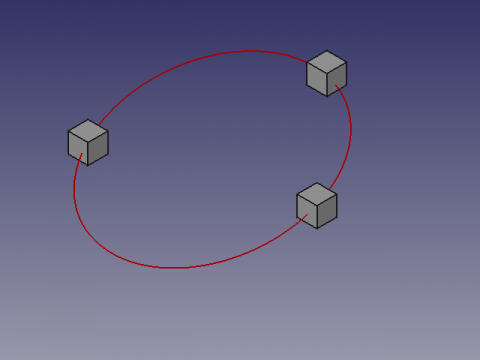
Dieses Makro erstellt einen Kreis an 3 ausgewählten Punkten im Raum. Die Punkte können Objekte wie Würfel oder Zylinder sein. Die ausgewählten Koordinaten bilden dann den Mittelpunkt dieser Formulare.
Verwenden Sie
Wählen Sie 3 Punkte oder Formulare in der 3D-Ansicht aus und führen Sie das Makro aus.
Wenn die Form eine Linie ist, ist die Koordinate der Mittelpunkt der Linie.
Grenzen
Die Reihenfolge der Auswahl der Angstformen beeinflusst den AXIS-Winkel und kehrt die Neigung des Kreises um. In diesem Fall können Sie die Reihenfolge der Auswahl der Formen umkehren oder ändern.
Die Koordinaten X, Y, Z des Werts 0 oder die Ausrichtung, die keine Berechnung zulässt, können eine Division durch einen Null-Fehler zurückgeben und mit "Die drei Punkte sind ausgerichtet" übersetzt.
Skript
Macro_Draft_Circle_3_Points_3D.FCMacro
# -*- coding: utf-8 -*-
# Create a circle from 3 points selected on the X, Y, Z map
# 04/03/2013
# From http://en.wikipedia.org/wiki/Circumscribed_circle

# 08/08/2014 PyQt4 and PySide

#OS: Windows Vista
#Word size: 32-bit
#Version: 0.14.3700 (Git)
#Branch: releases/FreeCAD-0-14
#Hash: 32f5aae0a64333ec8d5d160dbc46e690510c8fe1
#Python version: 2.6.2
#Qt version: 4.5.2
#Coin version: 3.1.0
#SoQt version: 1.4.1
#OCC version: 6.5.1

try:
    import PyQt4
    from PyQt4 import QtCore, QtGui
except Exception:
    import PySide
    from PySide import QtCore, QtGui
from math import pi, asin
import Draft, FreeCAD, FreeCADGui
from FreeCAD import Base

def errorDialog(msg):
    # Create a simple dialog QMessageBox
    # The first argument indicates the icon used: one of QtGui.QMessageBox.{NoIcon, Information, Warning, Critical, Question}
    diag = QtGui.QMessageBox(QtGui.QMessageBox.Critical,u"Error Message",msg)
    diag.setWindowModality(QtCore.Qt.ApplicationModal)
    diag.exec_()

def affiche(x,y,z,r,angle):
    diag = QtGui.QMessageBox(QtGui.QMessageBox.Information,u"Coordinates",u"Coordinate X : "+str(x)+"\r\n"+u"Coordinate Y : "+str(y)+"\n"+u"Coordinate Z : "+str(z)+"\nRadius\t   : "+str(r)+"\nAngle\t   : "+str(angle))
    diag.setWindowModality(QtCore.Qt.ApplicationModal)
    diag.setWindowModality(QtCore.Qt.NonModal)
    diag.exec_()

# objects selected
sel = FreeCADGui.Selection.getSelection()
# If there are 3 selected points so...
if len(sel)==3 :
    # Assignment of variables
    P1 = sel[0].Shape.BoundBox.Center
    P2 = sel[1].Shape.BoundBox.Center
    P3 = sel[2].Shape.BoundBox.Center

    P1P2 = (P2 - P1).Length
    P2P3 = (P3 - P2).Length
    P3P1 = (P1 - P3).Length

    # Circle radius.
    l = ((P1 - P2).cross(P2 - P3)).Length
    try:
        #if l < 1e-8:
        #    errorDialog("The three points are aligned")
        r = P1P2 * P2P3 * P3P1 / 2 / l
    except:
        errorDialog("The three points are aligned")
    else:
        # Sphere center.
        a = P2P3**2 * (P1 - P2).dot(P1 - P3) / 2 / l**2
        b = P3P1**2 * (P2 - P1).dot(P2 - P3) / 2 / l**2
        c = P1P2**2 * (P3 - P1).dot(P3 - P2) / 2 / l**2
        P1.multiply(a)
        P2.multiply(b)
        P3.multiply(c)
        PC = P1 + P2 + P3

        # Creation of a circle
        pl = Base.Placement()
        v = (P1 - P2).cross(P3 - P2)
        v.normalize()
        axis = Base.Vector(0, 0, 1).cross(v)
        angle = asin(axis.Length) * 180 / pi
        axis.normalize()
        pl = Base.Placement(PC, axis, angle)
        Draft.makeCircle(r, placement=pl, face=False, support=None)
        # Displays the result in the windows
        affiche((PC.x),(PC.y),(PC.z),r,angle)
        # Displays the result in the FreeCAD report view
        #FreeCAD.Console.PrintMessage("Coordinate X : "+str(PC.x)+"\n")
        #FreeCAD.Console.PrintMessage("Coordinate Y : "+str(PC.y)+"\n")
        #FreeCAD.Console.PrintMessage("Coordinate Z : "+str(PC.z)+"\n")
        #FreeCAD.Console.PrintMessage("Radius       : "+str(r)+"\n")
        #FreeCAD.Console.PrintMessage("Angle        : "+str(angle)+"\n")
else:
    # If the condition is not met, repeat
    #FreeCAD.Console.PrintError("Select 3 points and repeat\n")
    errorDialog("Select 3 points and repeat\n")
