Macro Draft Circle 3 Points 3D/de: Difference between revisions
mNo edit summary |
mNo edit summary |
||
| Line 1: | Line 1: | ||
{{Macro/de|Icon=Macro_Draft_Circle_3_Points|Name=Macro Draft Circle 3 Points 3D|Name/de=Macro Draft Circle 3 Points 3D|Description=Creates a circle from 3 selected points in the space.|Author=galou_breizh|Version=01.00|Date= |
{{Macro/de|Icon=Macro_Draft_Circle_3_Points|Name=Macro Draft Circle 3 Points 3D|Name/de=Macro Draft Circle 3 Points 3D|Description=Creates a circle from 3 selected points in the space.|Author=galou_breizh|Version=01.00|Date=2013-03-16}} |
||
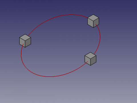
This macro creates a circle on 3 selected points in the space. The points can be objects such as cubes, cylinder, then selected coordinates will be the centre of these forms. |
This macro creates a circle on 3 selected points in the space. The points can be objects such as cubes, cylinder, then selected coordinates will be the centre of these forms. |
||
Revision as of 10:42, 30 September 2017
|
File:Macro Draft Circle 3 Points Macro Draft Circle 3 Points 3D |
| Beschreibung |
|---|
| Creates a circle from 3 selected points in the space. Versionsmakro : 01.00 Datum der letzten Änderung : 2013-03-16 Autor: galou_breizh |
| Autor |
| galou_breizh |
| Herunterladen |
| None |
| Links |
| Makros Rezepte Wie installiere ich Makros So passen Sie Symbolleisten an |
| Macro-Version |
| 01.00 |
| Datum der letzten Änderung |
| 2013-03-16 |
| FreeCAD-Version(s) |
| None |
| Standardverknüpfung |
| None |
| Siehe auch |
| None |
This macro creates a circle on 3 selected points in the space. The points can be objects such as cubes, cylinder, then selected coordinates will be the centre of these forms.
Use
Select 3 points, or forms in the 3D view and run the macro.
If the shape is a line, the coordinate will be the center of the line.
Limits
The order of selection of fear forms influencing the AXIS angle and reverse the inclination of the circle. In this case, reverse or change the order of selection of the shapes.
The coordinates X, Y, Z of value 0 or alignment not allowing not calculating, can return a division by zero error, and translated as "The three points are aligned"
Script
# -*- coding: utf-8 -*-
# Create a circle from 3 points selected on the X, Y, Z map
# 04/03/2013
# From http://en.wikipedia.org/wiki/Circumscribed_circle

# 08/08/2014 PyQt4 and PySide

#OS: Windows Vista
#Word size: 32-bit
#Version: 0.14.3700 (Git)
#Branch: releases/FreeCAD-0-14
#Hash: 32f5aae0a64333ec8d5d160dbc46e690510c8fe1
#Python version: 2.6.2
#Qt version: 4.5.2
#Coin version: 3.1.0
#SoQt version: 1.4.1
#OCC version: 6.5.1

try:
    import PyQt4
    from PyQt4 import QtCore, QtGui
except Exception:
    import PySide
    from PySide import QtCore, QtGui
from math import pi, asin
import Draft, FreeCAD, FreeCADGui
from FreeCAD import Base

def errorDialog(msg):
    # Create a simple dialog QMessageBox
    # The first argument indicates the icon used: one of QtGui.QMessageBox.{NoIcon, Information, Warning, Critical, Question}
    diag = QtGui.QMessageBox(QtGui.QMessageBox.Critical,u"Error Message",msg)
    diag.setWindowModality(QtCore.Qt.ApplicationModal)
    diag.exec_()

def affiche(x,y,z,r,angle):
    diag = QtGui.QMessageBox(QtGui.QMessageBox.Information,u"Coordinates",u"Coordinate X : "+str(x)+"\r\n"+u"Coordinate Y : "+str(y)+"\n"+u"Coordinate Z : "+str(z)+"\nRadius\t   : "+str(r)+"\nAngle\t   : "+str(angle))
    diag.setWindowModality(QtCore.Qt.ApplicationModal)
    diag.setWindowModality(QtCore.Qt.NonModal)
    diag.exec_()

# objects selected
sel = FreeCADGui.Selection.getSelection()
# If there are 3 selected points so...
if len(sel)==3 :
    # Assignment of variables
    P1 = sel[0].Shape.BoundBox.Center
    P2 = sel[1].Shape.BoundBox.Center
    P3 = sel[2].Shape.BoundBox.Center

    P1P2 = (P2 - P1).Length
    P2P3 = (P3 - P2).Length
    P3P1 = (P1 - P3).Length

    # Circle radius.
    l = ((P1 - P2).cross(P2 - P3)).Length
    try:
        #if l < 1e-8:
        #    errorDialog("The three points are aligned")
        r = P1P2 * P2P3 * P3P1 / 2 / l
    except:
        errorDialog("The three points are aligned")
    else:
        # Sphere center.
        a = P2P3**2 * (P1 - P2).dot(P1 - P3) / 2 / l**2
        b = P3P1**2 * (P2 - P1).dot(P2 - P3) / 2 / l**2
        c = P1P2**2 * (P3 - P1).dot(P3 - P2) / 2 / l**2
        P1.multiply(a)
        P2.multiply(b)
        P3.multiply(c)
        PC = P1 + P2 + P3

        # Creation of a circle
        pl = Base.Placement()
        v = (P1 - P2).cross(P3 - P2)
        v.normalize()
        axis = Base.Vector(0, 0, 1).cross(v)
        angle = asin(axis.Length) * 180 / pi
        axis.normalize()
        pl = Base.Placement(PC, axis, angle)
        Draft.makeCircle(r, placement=pl, face=False, support=None)
        # Displays the result in the windows
        affiche((PC.x),(PC.y),(PC.z),r,angle)
        # Displays the result in the FreeCAD report view
        #FreeCAD.Console.PrintMessage("Coordinate X : "+str(PC.x)+"\n")
        #FreeCAD.Console.PrintMessage("Coordinate Y : "+str(PC.y)+"\n")
        #FreeCAD.Console.PrintMessage("Coordinate Z : "+str(PC.z)+"\n")
        #FreeCAD.Console.PrintMessage("Radius       : "+str(r)+"\n")
        #FreeCAD.Console.PrintMessage("Angle        : "+str(angle)+"\n")
else:
    # If the condition is not met, repeat
    #FreeCAD.Console.PrintError("Select 3 points and repeat\n")
    errorDialog("Select 3 points and repeat\n")