Macro Draft Circle 3 Points/fr: Difference between revisions
(Created page with "==Utilisation== Sélectionnez 3 points, ou formes dans la vue 3D et lancez la macro.<br /> Si le shape est une ligne, le point sera le centre de la ligne.") |
(Created page with "==Options== Si l'objet sélectionné a différents plans, (xy '''Z10''', xy '''Z2''', xy '''Z5''') le cercle est construit aux coordonnées x,y '''Z=0'''.<br /> Si tous le obj...") |
||
| Line 11: | Line 11: | ||
==Options== |
==Options== |
||
Si l'objet sélectionné a différents plans, (xy '''Z10''', xy '''Z2''', xy '''Z5''') le cercle est construit aux coordonnées x,y '''Z=0'''.<br /> |
|||
Si tous le objets sélectionnés ont la même hauteur Z ex: (xy '''Z5''', xy '''Z5''', xy '''Z5'''), le ercle est construit sur le pla x,y '''Z=5'''. |
|||
==Script== |
==Script== |
||
Revision as of 17:04, 25 September 2017
|
File:Macro Draft Circle 3 Points Macro Make Circle 3 Points |
| Description |
|---|
| Crée un cercle à partir de 3 points ou trois objets sélectionnés. Version macro : 01.00 Date dernière modification : 11/03/2013 Auteur: Mario52 |
| Auteur |
| Mario52 |
| Téléchargement |
| None |
| Liens |
| Page des macros Comment installer une macro Comment créer une barre d'outils |
| Version Macro |
| 01.00 |
| Dernière modification |
| 11/03/2013 |
| Version(s) FreeCAD |
| None |
| Raccourci clavier |
| None |
| Voir aussi |
| None |
Description
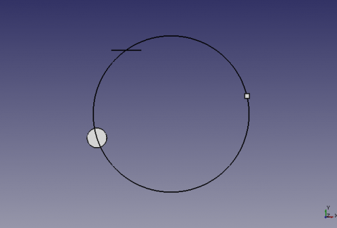
Cette macro crée un cercle sur 3 points. Si trois objets sont sélectionnés le centre de ces formes seront les points du cercle.
Utilisation
Sélectionnez 3 points, ou formes dans la vue 3D et lancez la macro.
Si le shape est une ligne, le point sera le centre de la ligne.
Options
Si l'objet sélectionné a différents plans, (xy Z10, xy Z2, xy Z5) le cercle est construit aux coordonnées x,y Z=0.
Si tous le objets sélectionnés ont la même hauteur Z ex: (xy Z5, xy Z5, xy Z5), le ercle est construit sur le pla x,y Z=5.
Script
Draft_Circle_3_Points.FCMacro
# -*- coding: utf-8 -*-
# créer un cercle à partir de 3 points sélectionnés sur le plan X,Y
# 04/03/2013
# la formule provient de
# http://www-obs.univ-lyon1.fr/labo/fc/Ateliers_archives/ateliers_2005-06/cercle_3pts.pdf
# lire la note dans le pdf, sur l'ordre de sélection des points,
# si la formule renvoie une erreur (exemple les 3 points dans le même alignement)
#
import Draft, Part, FreeCAD, math, PartGui, FreeCADGui
from math import sqrt, pi, sin, cos
from FreeCAD import Base

# prendre les objets sélectionnés
sel = FreeCADGui.Selection.getSelection()
i=0
centreX=0
centreY=0
rayon=0
# S'il y a 3 points sélectionnés alors..
if len(sel)==3 :
	i=0
	ta=[0,0,0,0,0,0,0,0,0]
	for obj in sel:
		x=(obj.Shape.BoundBox.Center)
		ta[i+0]=(x.x)
		ta[i+1]=(x.y)
		ta[i+2]=(x.z)
		i=i+3
# Affectation des variables
	x_point_1=ta[0]
	y_point_1=ta[1]
	z_point_1=ta[2]

	x_point_2=ta[3]
	y_point_2=ta[4]
	z_point_2=ta[5]

	x_point_3=ta[6]
	y_point_3=ta[7]
	z_point_3=ta[8]
# Calcul des coordonnées du centre du cercle
	centreX =((x_point_3**2-x_point_2**2+y_point_3**2-y_point_2**2)/(2*(y_point_3-y_point_2))-(x_point_2**2-x_point_1**2+y_point_2**2-y_point_1**2)/(2*(y_point_2-y_point_1)))/((x_point_3-x_point_2)/(y_point_3-y_point_2)-(x_point_2-x_point_1)/(y_point_2-y_point_1))
	centreY =-(x_point_2-x_point_1)/(y_point_2-y_point_1)*centreX+(x_point_2**2-x_point_1**2+y_point_2**2-y_point_1**2)/(2*(y_point_2-y_point_1))
	rayon =sqrt((x_point_1-centreX)**2+(y_point_1-centreY)**2)
# Définition de la coordonnée Z
# Si toutes les coordonnées Z sont égales le centreZ s'aligne à la coordonnée Z
	if z_point_1==z_point_2 and z_point_2==z_point_3:
		centreZ=z_point_1
	else:
# Si une coordonnée est différente alors Z=0
		centreZ=0
# Création du cercle
	pl=FreeCAD.Placement()
	pl.Rotation.Q=(0.0,-0.0,-0.0,1.0)
	pl.Base=FreeCAD.Vector(centreX,centreY,centreZ)
	Draft.makeCircle((rayon),placement=pl,face=False,support=None)
# Affiche le résultat dans la Vue rapport de FreeCAD
	FreeCAD.Console.PrintMessage("Coordonnée X : "+str(centreX)+"\r\n")
	FreeCAD.Console.PrintMessage("Coordonnée Y : "+str(centreY)+"\r\n")
	FreeCAD.Console.PrintMessage("Coordonnée Z : "+str(centreZ)+"\r\n")
	FreeCAD.Console.PrintMessage("Rayon        : "+str(rayon  )+"\r\n")
else:
# Si la condition n'est pas remplie, recommencer
	FreeCAD.Console.PrintError("Sélectionnez 3 points et recommencez\r\n")
Improved version
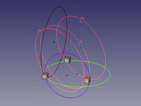
In addition to the previous features, this example is used to align an orthogonal circle on each shape in the selection, and the plan "'XY, YZ, XZ ' ' chosen.
The circle takes the color of the axis dedicated regardless of current color, and the center point of the circle is drawn (option O/N).
-
Cercle circonscrit sur 3 formes,
-
de manière orthogonale sur la forme choisie
-
-
The settings to change.
# Change the values here below
			# mode by default vueChoix = 0 and alignerSur = 0
	vueChoix=0	# choice of the top view = 1 XY, view Front = 2 ZX, Right view = 3 ZY
	alignerSur=0	# Aligns the circle shaped the choice (1,2 or 3) or Z = 0
	afficherPoint=1	# Displays the center point of the circle
# -*- coding: utf-8 -*-
# créer un cercle à partir de 3 points séléctionnés
# avec comme options le cercle peut être construit sur un plans au choix
# à la coordonnée d'une des trois formes sélectionnées au choix
# et création du point central O/N
# 04/03/2013
# la formule provient de
# http://www-obs.univ-lyon1.fr/labo/fc/Ateliers_archives/ateliers_2005-06/cercle_3pts.pdf
# lire la note dans le pdf, sur l'ordre de sélection des points,
# si la formule renvoie une erreur (exemple les 3 points dans le même alignement)
#
import Draft, Part, FreeCAD, math, PartGui, FreeCADGui
from math import sqrt, pi, sin, cos
from FreeCAD import Base
from PyQt4 import QtCore, QtGui
def errorDialog(msg):
# Create a simple dialog QMessageBox
# The first argument indicates the icon used: one of QtGui.QMessageBox.{NoIcon, Information, Warning, Critical, Question}
diag = QtGui.QMessageBox(QtGui.QMessageBox.Critical,u"Error Message",msg)
diag.setWindowModality(QtCore.Qt.ApplicationModal)
diag.exec_()
def affiche(x,y,z,rayon,r,v,b,afficherPoint):
pl.Base=FreeCAD.Vector(x,y,z)
Draft.makeCircle((rayon),placement=pl,face=False,support=None)
FreeCADGui.activeDocument().activeObject().LineColor = (r,v,b)
if afficherPoint==1:
Draft.makePoint(x,y,z)
diag = QtGui.QMessageBox(QtGui.QMessageBox.Information,u"Coordinates",u"Coordinates X : "+str(x)+"\r\n"+u"Coordinates Y : "+str(y)+"\n"+u"Coordinates Z : "+str(z)+"\nRayon\t : "+str(rayon))
diag.setWindowModality(QtCore.Qt.ApplicationModal)
diag.exec_()
# prendre les objets selectionnes
sel = FreeCADGui.Selection.getSelection()
i=0
centreX=0;centreY=0;rayon=0
# S'il y a 3 points sélectionnés alors..
if len(sel)==3 :
i=0
ta=[0,0,0,0,0,0,0,0,0]
for obj in sel:
x=(obj.Shape.BoundBox.Center)
ta[i+0]=(x.x)
ta[i+1]=(x.y)
ta[i+2]=(x.z)
i=i+3
# Change the values here below
# mode by default vueChoix = 0 and alignerSur = 0
vueChoix=0 # choice of the top view = 1 XY, view Front = 2 ZX, Right view = 3 ZY
alignerSur=0 # Aligns the circle shaped the choice (1,2 or 3) or Z = 0
afficherPoint=1 # Displays the center point of the circle
# Affectation des variables
if vueChoix==3: # View of right ZY (Red)
z_point_1=ta[0]
x_point_1=ta[1]
y_point_1=ta[2]
z_point_2=ta[3]
x_point_2=ta[4]
y_point_2=ta[5]
z_point_3=ta[6]
x_point_3=ta[7]
y_point_3=ta[8]
elif vueChoix==2: # Front view ZX (Green)
y_point_1=ta[0]
z_point_1=ta[1]
x_point_1=ta[2]
y_point_2=ta[3]
z_point_2=ta[4]
x_point_2=ta[5]
y_point_3=ta[6]
z_point_3=ta[7]
x_point_3=ta[8]
else: # Top view XY (blue)
x_point_1=ta[0]
y_point_1=ta[1]
z_point_1=ta[2]
x_point_2=ta[3]
y_point_2=ta[4]
z_point_2=ta[5]
x_point_3=ta[6]
y_point_3=ta[7]
z_point_3=ta[8]
# Calculation of coordinates of the center of the circle
try:
centreX =((x_point_3**2-x_point_2**2+y_point_3**2-y_point_2**2)/(2*(y_point_3-y_point_2))-(x_point_2**2-x_point_1**2+y_point_2**2-y_point_1**2)/(2*(y_point_2-y_point_1)))/((x_point_3-x_point_2)/(y_point_3-y_point_2)-(x_point_2-x_point_1)/(y_point_2-y_point_1))
centreY =-(x_point_2-x_point_1)/(y_point_2-y_point_1)*centreX+(x_point_2**2-x_point_1**2+y_point_2**2-y_point_1**2)/(2*(y_point_2-y_point_1))
rayon =sqrt((x_point_1-centreX)**2+(y_point_1-centreY)**2)
except:
errorDialog(u"Impossible calculation too aligned elements")
else:
#finally: sera TOUJOURS exécuté
# Definition of the coordinate Z
centreZ=0
# Création du cercle
pl=FreeCAD.Placement()
if vueChoix==1: # Plan XY Dessus
pl.Rotation.Q=(0,0,0,1.0)
if alignerSur==1:
affiche(centreX,centreY,z_point_1,rayon,0.0,0.0,1.0,afficherPoint)
elif alignerSur==2:
affiche(centreX,centreY,z_point_2,rayon,0.0,0.0,1.0,afficherPoint)
elif alignerSur==3:
affiche(centreX,centreY,z_point_3,rayon,0.0,0.0,1.0,afficherPoint)
elif vueChoix==2: # Plan XZ Face
pl.Rotation.Q=(1,0,0,1.0)
if alignerSur==1:
affiche(centreY,z_point_1,centreX,rayon,0.0,1.0,0.0,afficherPoint)
elif alignerSur==2:
affiche(centreY,z_point_2,centreX,rayon,0.0,1.0,0.0,afficherPoint)
elif alignerSur==3:
affiche(centreY,z_point_3,centreX,rayon,0.0,1.0,0.0,afficherPoint)
elif vueChoix==3: # Plan YZ Droite
pl.Rotation.Q=(0,1,0,1.0)
if alignerSur==1:
affiche(z_point_1,centreX,centreY,rayon,1.0,0.0,0.0,afficherPoint)
elif alignerSur==2:
affiche(z_point_2,centreX,centreY,rayon,1.0,0.0,0.0,afficherPoint)
elif alignerSur==3:
affiche(z_point_3,centreX,centreY,rayon,1.0,0.0,0.0,afficherPoint)
else: # modifier pour avoir XYZ
# si les coordonnées Z sont égales alors le cercle s'aligne à Z
if z_point_1==z_point_2 and z_point_2==z_point_3:
centreZ=z_point_1
affiche(centreX,centreY,z_point_1,rayon,0.0,0.0,0.0,afficherPoint)
else:
# Si une coordonnée est différente alors Z=0
affiche(centreX,centreY,0,rayon,0.0,0.0,0.0,afficherPoint)
else:
# Si la condition n'est pas remplie, recommencer
errorDialog(u"Select 3 points and repeat")
#FreeCAD.Console.PrintError("Select 3 points and repeatr\n")Anaglyphe
Here an Anaglyph view that allows you to see two different positions of the view by using glasses with filters red and Cyan ![]() .
.
Watch alternately with the left eye and the right eye to see the views separately.
Credits
The genesis of the macro Draft Circle 3 Points on the forum (PYTHON) coordonnées d'un point helped flachyjoe thanks.
The formula comes from cercle_3pts.pdf and used with the kind permission of its author.
