Macro CenterFace
|
File:Text-x-python Macro CenterFace |
| Description |
|---|
| Cette macro crée un point rouge (éditable) au centre (mass) de la face sélectionnée et affiche ses coordonnées dans la vue rapport. Auteur: Mario52 |
| Auteur |
| Mario52 |
| Téléchargement |
| None |
| Liens |
| Page des macros Comment installer une macro Comment créer une barre d'outils |
| Version Macro |
| 1.0 |
| Dernière modification |
| None |
| Version(s) FreeCAD |
| None |
| Raccourci clavier |
| None |
| Voir aussi |
| None |
Description
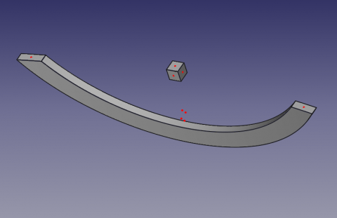
Cette macro crée un point rouge (éditable) au centre (mass) de la face sélectionnée et affiche ses coordonnées dans la vue rapport.
Utilisation
Sélectionnez un face de votre objet et lancez la macro. Un point rouge (couleur modifiable) sera créé au centre (mass) de la face sélectionnée et les coordonnées XYZ de ce point seront affichés dans la vue rapport ainsi que la surface de la face et ses coordonnées.
Pour changer la couleur du point, modifiez les lignes 36, 37, 38
    red   = 1.0  # 1 = 255
    green = 0.0  #
    blue  = 0.0  #
Le centre de la face et les coordonnées XYZ de ce centre seront affichés dans la vue rapport ainsi que la surface de la face et ses coordonnées.
Icone
Download the file image and copy in your macro repertory.
Click the image, in the new window position the mouse over the image, click the right mouse and do "Save target as ..."
Macro
Macro_CenterFace.FCMacro
# -*- coding: utf-8 -*-
# 29/04/2014
# select a face launch and list the center coordinate XYZ of face
# To change the color of the dot change the lines 36, 37, 38
# red   = 1.0  # 1 = 255
# green = 0.0  #
# blue  = 0.0  #
# Macro_CenterFace
# Mario52

#OS: Windows Vista
#Platform: 32-bit
#Version: 0.14.3389
#Python version: 2.6.2
#Qt version: 4.5.2
#Coin version: 3.1.0
#SoQt version: 1.4.1
#OCC version: 6.5.1

import FreeCAD, FreeCADGui, Draft, Part

try:
    sel = FreeCADGui.Selection.getSelection()             # get the selection
    sh = sel[0].Shape                                     # seletion of the first element

    App.Console.PrintMessage("Label : "+ str(sel[0].Label)+"\n")     # extract the Label
    App.Console.PrintMessage("Name  : "+ str(sel[0].Name) +"\n")     # extract the Name
except:
    App.Console.PrintError( "select a face"+"\n")


try:
    SubElement = FreeCADGui.Selection.getSelectionEx()# "getSelectionEx" Used for selecting subobjects
    element_ = SubElement[0].SubElementNames[0]       # seletion of the first element

#    print element_
#    print sh.Faces

    # LineColor
    red   = 1.0  # 1 = 255
    green = 0.0  #
    blue  = 0.0  #

    for i in range(len(sh.Faces)):                    # list and extract the data
        App.Console.PrintMessage( "Center Face "+str(i)+" "+str(sh.Faces[i].CenterOfMass)+"\n") # Vector center mass to face
#        print "X : ",sh.Faces[i].CenterOfMass.x                                                # Coord. X center mass to face
#        print "Y : ",sh.Faces[i].CenterOfMass.y                                                # Coord. Y center mass to face
#        print "Z : ",sh.Faces[i].CenterOfMass.z                                                # Coord. Z center mass to face
        Draft.makePoint(sh.Faces[i].CenterOfMass.x,sh.Faces[i].CenterOfMass.y,sh.Faces[i].CenterOfMass.z) # create a point
        FreeCADGui.activeDocument().activeObject().PointColor = (red, green, blue)

        App.Console.PrintMessage( "       Surface   : "+str(sel[0].Shape.Faces[i-1].Area)+"\n")
        fco = 0
        for f0 in sel[0].Shape.Faces[i].Vertexes:      # Vertexes faces
            fco += 1
            App.Console.PrintMessage("       Vertexe X"+str(fco)+": "+str(f0.Point.x)+" Y"+str(fco)+": "+str(f0.Point.y)+" Z"+str(fco)+": "+str(f0.Point.z)+"\n")

except:
    App.Console.PrintError( "select a face *"+"\n")
